Radio frequency matching circuit and radio frequency system
A technology of radio frequency matching and matching circuit, which is applied in the field of radio frequency matching circuit and radio frequency system, can solve the problems of reducing the complexity of the impedance matching network and failing to improve the power loss in the wide frequency band, so as to shorten the radio frequency debugging time and speed up the research and development Progress, the effect of filtering out harmonic interference
- Summary
- Abstract
- Description
- Claims
- Application Information
AI Technical Summary
Problems solved by technology
Method used
Image

Examples
Embodiment 1
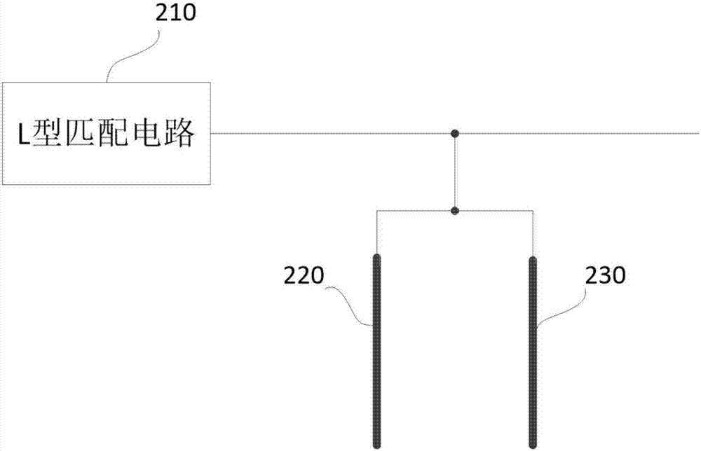
[0035] like Figure 1-2 As shown, this embodiment provides a radio frequency matching circuit, and the radio frequency matching circuit includes: an L-shaped matching circuit 210, a first transmission line 220, and a second transmission line 230, and the first transmission line 220 and the second transmission line 230 are connected Two sections of open transmission lines in parallel are formed, a transmission line connection point is formed between the first transmission line 220 and the second transmission line 230 , and the transmission line connection point is connected to the L-shaped matching circuit 210 . When one end of the transmission line is open, the impedance of the other end will be infinitely small, which can meet the loss of less power. Therefore, the connected transmission line in the circuit design of this embodiment is set to be open.
[0036] Cables for transmitting radio frequency signals are generally called transmission lines, and there are two commonly u...
Embodiment 2
[0040] The difference between this embodiment and the previous embodiments is that this embodiment provides a radio frequency matching circuit with better broadband matching performance, wherein the lengths of the first transmission line 220 and the second transmission line 230 are different. The characteristics of a transmission line are usually related to the number of wavelengths of the length, and people usually use the number of wavelengths to describe the length of the transmission line, rather than the absolute length, so the length here is defined as the number of wavelengths.
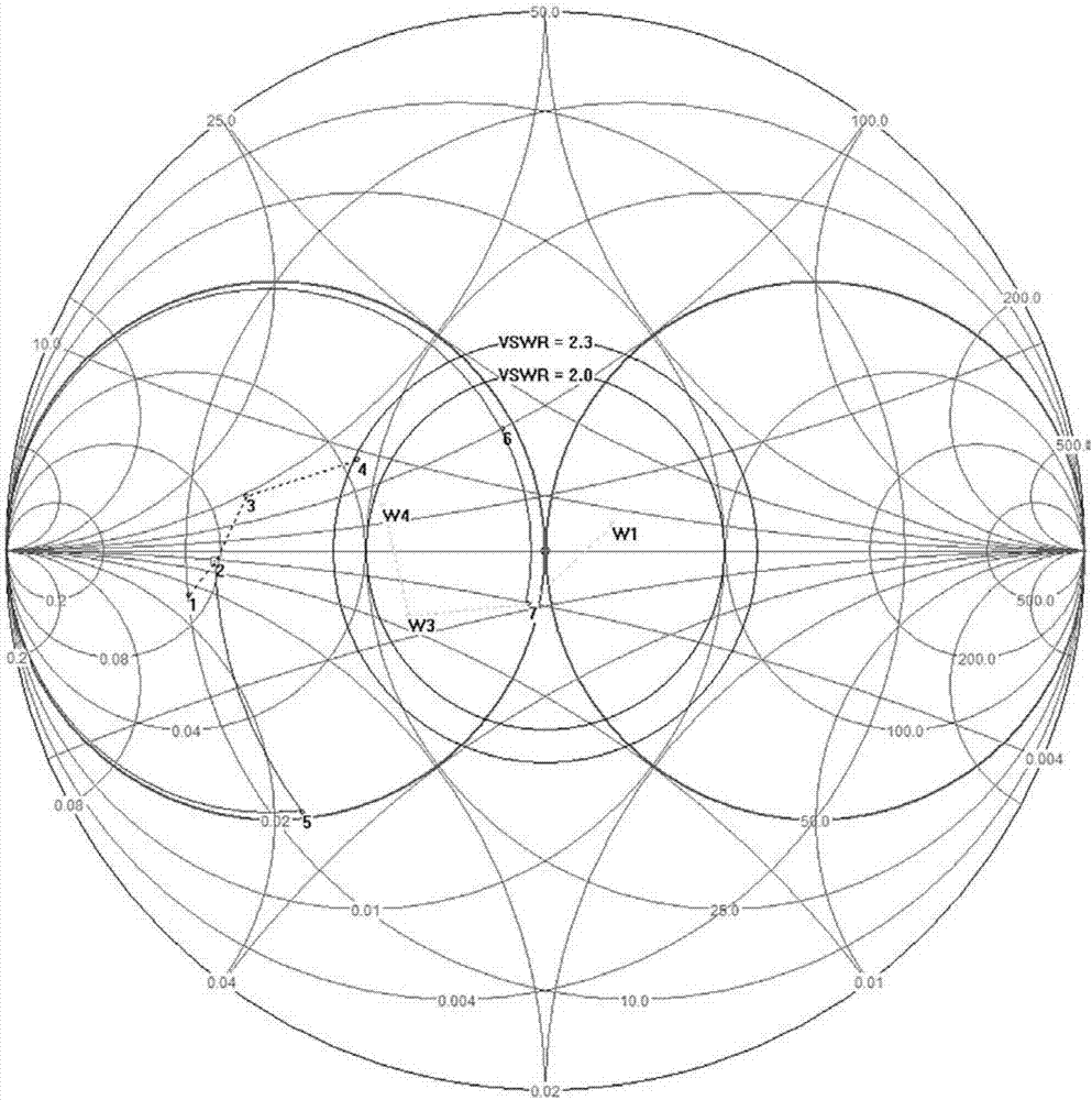
[0041] Experimental data proves that when the lengths of the first transmission line 220 and the second transmission line 230 are different, better radio frequency matching effects can be produced, especially for wide-screen radio frequency signals, which can greatly reduce the power loss of radio frequency signals during transmission. Keep the voltage standing wave ratio (VSWR) at the different...
Embodiment 3
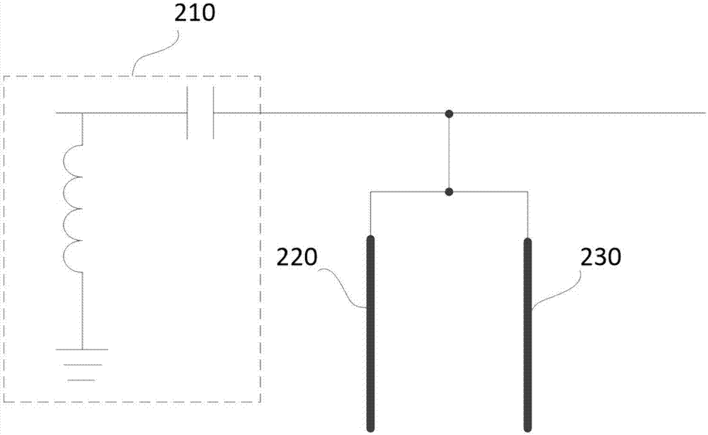
[0045] like Figure 4-Figure 7 As shown, the difference between this embodiment and Embodiment 2 is that this embodiment provides more combinations of components of the L-shaped matching circuit in a radio frequency matching circuit, and the L-shaped matching circuit 210 includes: a first matching element 211 and A second matching element 212 , one end of the first matching element 211 is grounded, and the other end is connected to the connection point of the transmission line through the second matching element 212 .
[0046] The first matching element 211 is a capacitor or an inductor, and the second matching element 212 is a capacitor or an inductor. Here, the first matching element 211 and the second matching element 212 are set as capacitors or inductors, which can be used to meet the matching of conventional signals and ensure greater transmission of signals. Among them, the capacitance value and inductance value depend on the working frequency band, and the capacitance...
PUM
 Abstract
Description
Claims
Application Information
 - Generate Ideas
- Intellectual Property
- Life Sciences
- Materials
- Tech Scout
- Unparalleled Data Quality
- Higher Quality Content
- 60% Fewer Hallucinations
Browse by: Latest US Patents, China's latest patents, Technical Efficacy Thesaurus, Application Domain, Technology Topic, Popular Technical Reports.
© 2025 PatSnap. All rights reserved.Legal|Privacy policy|Modern Slavery Act Transparency Statement|Sitemap|About US| Contact US: help@patsnap.com