Setup for testing bifacial solar cells

A solar cell and double-sided technology, which is applied in the fields of electrical components, photovoltaic power generation, and photovoltaic system monitoring. Effects of interaction, reduced number of uses, accurate test results

Active Publication Date: 2019-08-13
DONGFANG HUANSHENG PHOTOVOLTAIC (JIANGSU) CO LTD
View PDF5 Cites 0 Cited by
  • Summary
  • Abstract
  • Description
  • Claims
  • Application Information

AI Technical Summary

Problems solved by technology

Although bifacial cells show obvious advantages in terms of module material usage and land saving, the problem of how to accurately measure the power of bifacial cells and modules has not been effectively resolved
This method needs to place a light source on the upper and lower sides. Although the power of the front and back sides of the battery or module can be tested at the same time, on the one hand, it puts forward higher requirements for the maintenance and use of the light source. Strong enhancement, causing the power test to be falsely high, affecting the accuracy of the test results

Method used


Image

  • Setup for testing bifacial solar cells
  • Setup for testing bifacial solar cells
  • Setup for testing bifacial solar cells

Examples


Embodiment 1

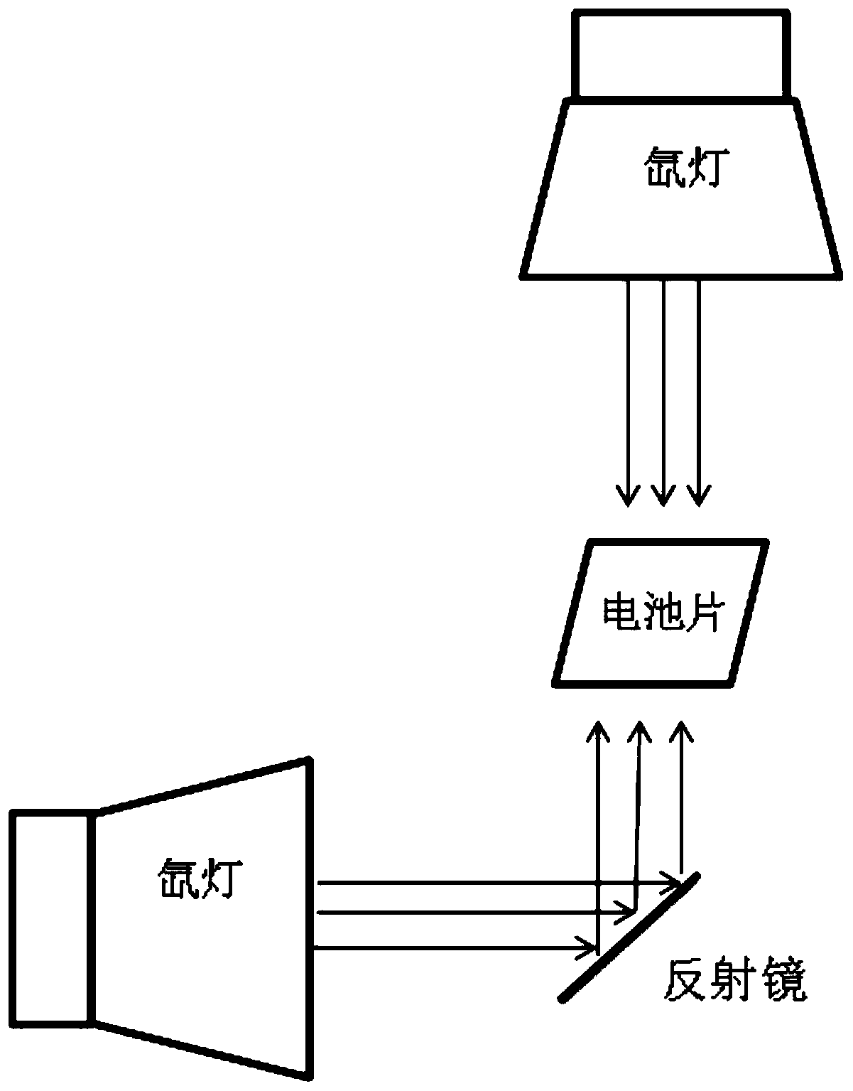
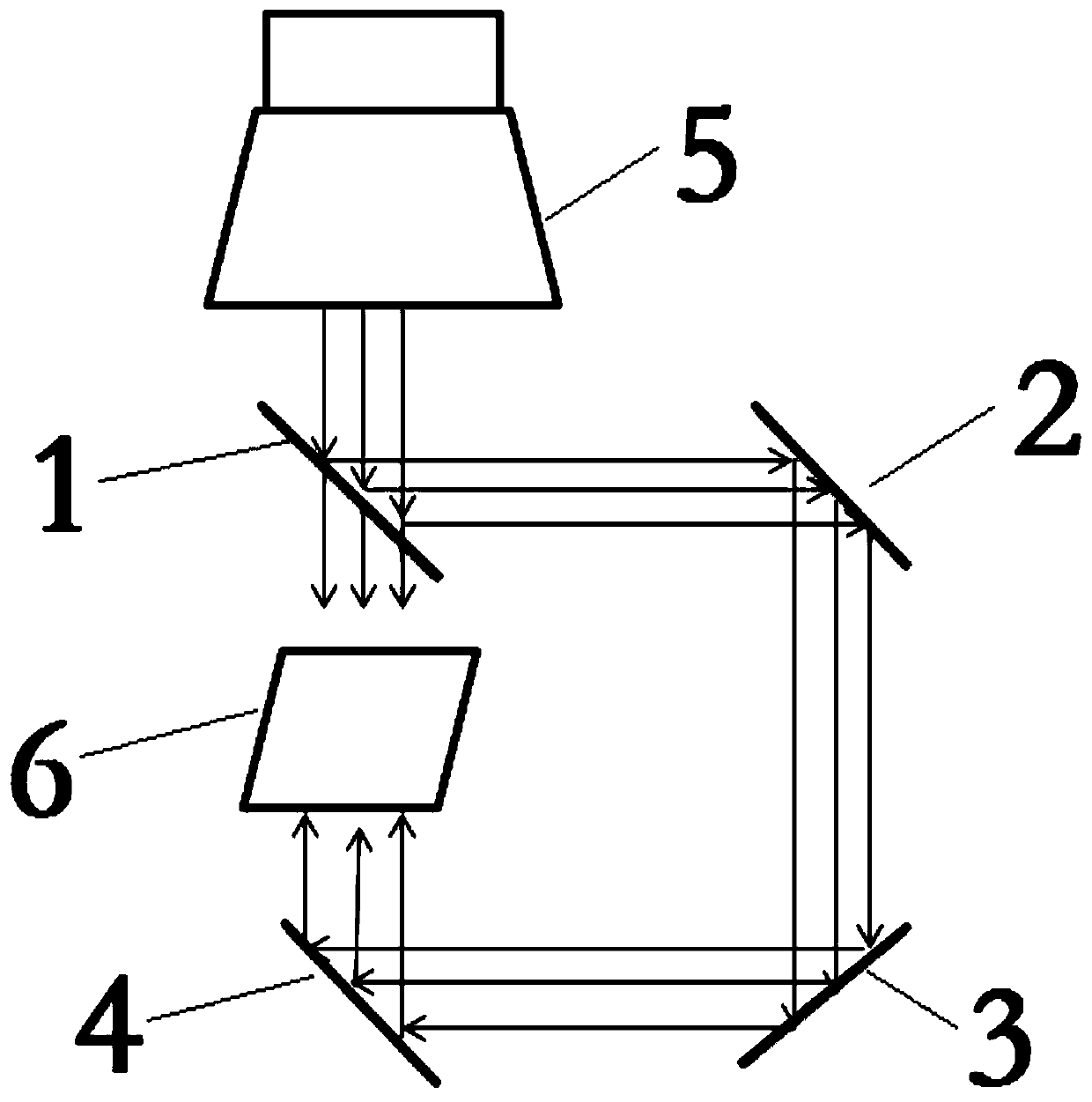
[0033] Example 1: Combination figure 2 , an apparatus for testing bifacial solar cells, including a xenon lamp 5,

[0034] The device also includes a first beam splitter 1 arranged directly under the xenon lamp 5, and the mirror surface of the first beam splitter 1 is arranged at 45° relative to the incident light of the xenon lamp 5;

[0035] The device also includes a second reflector 2 whose mirror surface and horizontal position are parallel to the first beam splitter 1, and the oblique top of the first beam splitter 1 corresponds to the reflection surface of the second reflector 2;

[0036] The device also includes a third reflector 3 positioned perpendicular to the second reflector 2, the third reflector 3 is disposed directly below the second reflector 2, and the reflection surface of the third reflector 3 is 45° upward and horizontal. The orientation is opposite to the horizontal orientation of the reflecting surface of the second mirror 2;

[0037] The device also ...

Embodiment 2

[0040] Embodiment 2: According to the device described in Embodiment 1, the first beam splitter 1 can be selected according to the light intensity requirements of the front and back of the battery sheet 6. If required, both the front and back sides use 1000W / m 2 The first beam splitter 1 can use an optical beam splitter with a beam splitting ratio of 50%: the transmittance and reflectivity are respectively 50%, so that half of the light source is transmitted and half is reflected. The device can be used to test the conversion efficiency of the front and back sides of the cell 6, and can also be used to test the power of the front and back sides of the module.

Embodiment 3

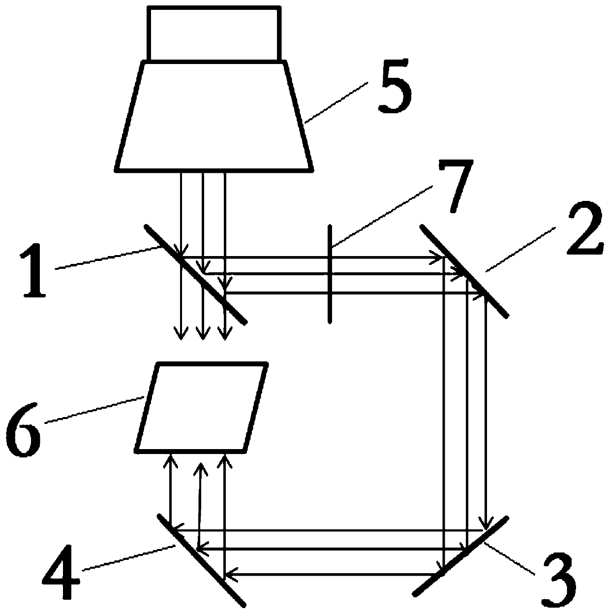
[0041] Example 3: Combination image 3 , as in the device described in Embodiment 1, in order to realize the different requirements for the light intensity on the back of the cell 6, a vertical light-transmitting plate 7 is added between the first beam splitter 1 and the second reflector 2, and the light transmission range is 50-95%.


PUM


Abstract

The invention discloses a device for testing a double-sided solar cell. According to the device, an optical beam splitter of the fixed beam splitting ratio is arranged at the position of 45 degrees below an upper light source. When the light passes the beam splitter, a part of light transmits to directly irradiate to the surface of the cell or the component, and the other part of light enters a reflecting mirror of 45 degrees through reflection to irradiate to the back surface of the cell through three reflecting mirrors of 45 degrees. According to the method, the situation of inaccurate single side test result of the cell or the component caused by the interaction of double light sources can be effectively avoided.

Description

technical field [0001] The invention relates to the field of photovoltaic solar cells, in particular to the field of solar cell testing, in particular to a device for testing double-sided solar cells. Background technique [0002] As the annual installed capacity continues to rise, resources such as land and roofs will increasingly become scarce resources. How to use limited land resources to maximize the power generation of modules has become a major problem faced by people. Bifacial cells have attracted more and more attention due to their characteristics of bifacial power generation. [0003] The advantages of double-sided solar cells are very obvious. First, both the front and back of the cell can receive light, and the annual power generation is 1.2 to 1.5 times that of ordinary single-sided solar cells; secondly, the front and back of the battery module are protected by tempered glass. Materials, good lighting, weather resistance, creativity, and high reliability; fi...

Claims


Application Information

Patent Timeline
Patent Type & Authority Patents(China)
IPC IPC(8): H02S50/15
CPCH02S50/15Y02E10/50
Inventor 李慧樊华徐建张子森彭彪俞超徐强
Owner DONGFANG HUANSHENG PHOTOVOLTAIC (JIANGSU) CO LTD
Why Eureka
Try Eureka