Print head assembly and 3D printing system
A three-dimensional printing and print head technology, applied in printing and other directions, can solve problems such as affecting printing accuracy, affecting printing accuracy and printing effect, and color loss, and achieve the effect of simplifying calculation, avoiding color loss, and avoiding overlapping
- Summary
- Abstract
- Description
- Claims
- Application Information
AI Technical Summary
Problems solved by technology
Method used
Image
Examples
Embodiment 2
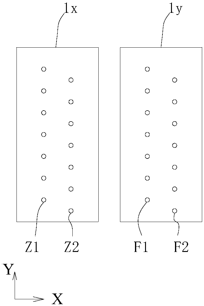
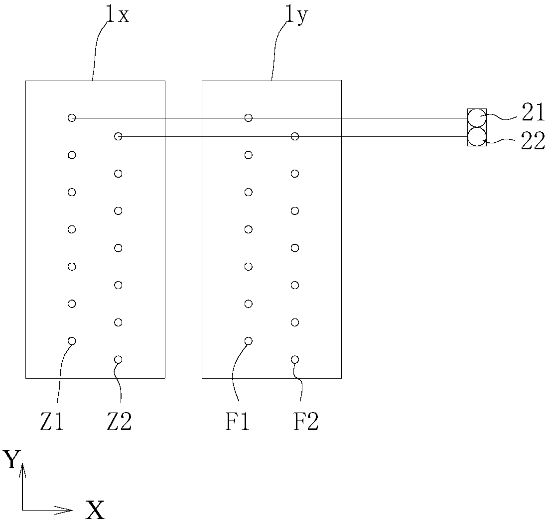
[0033] In addition, the number of auxiliary material channels is not necessarily the same as the number of main material channels. For example, the print head assembly also includes at least one auxiliary material channel. The area of the deposited ink droplet is different. Figure 3a It is a schematic structural diagram of another print head assembly provided in Embodiment 2 of the present invention. Such as Figure 3a As shown, the difference between this embodiment and the first embodiment is that, in addition to the main material passages Z1, Z2 and F1, F2 correspondingly provided in the first embodiment, two auxiliary material passages F3 and F4 are also provided. Auxiliary material channels F1, F2, F3 and F4 are arranged sequentially in the main scanning direction X, and their nozzle holes are aligned with each other in the main scanning direction X, but arranged in a dislocation in the sub-scanning direction Y. In this embodiment, the number of ink droplets that can...
Embodiment 3
[0037] Similarly, the print head in the print head assembly can also be a single-channel print head. Figure 4 It is a structural schematic diagram of another print head assembly provided by Embodiment 3 of the present invention. Compared with Embodiment 1, this embodiment differs in that, in this embodiment, all four print heads are single-channel print heads. Specifically, two print heads 4x are respectively set as main material channels Z1 and Z2, and two print heads 4y are respectively set as auxiliary material channels F1 and F2, wherein the nozzle holes of Z1 and F1 channels are aligned in the main scanning direction X. The nozzle hole arrays of Z2 and F2 are also aligned in the main scanning direction X, and the nozzle holes of Z1 and Z2 are arranged in sequence along the main scanning direction X, but they are misaligned in the sub-scanning direction Y. F1 and F2 are arranged in the same Arranged in a manner, the working principle of each material channel is consisten...
Embodiment 4
[0041] During 3D printing, sometimes due to the structure and shape of the object to be printed, it is necessary to use support materials to temporarily support and fill the structure, and after the printing is completed, the main material and auxiliary materials are cured and formed. Remove support material. Figure 5 It is a schematic structural diagram of the fourth print head assembly provided by Embodiment 4 of the present invention. Such as Figure 5 As shown, the difference between this embodiment and the first embodiment is that, in order to carry out ejection and printing of the support material, the print head assembly further includes at least one support material channel, and the support material channel can be used for ejection after the printing is completed. Support material removed later. Specifically, the support material channel for ejecting the support material may be located on the same print head as the main material channel or the auxiliary material cha...
PUM
 Abstract
Description
Claims
Application Information
 - R&D Engineer
- R&D Manager
- IP Professional
- Industry Leading Data Capabilities
- Powerful AI technology
- Patent DNA Extraction
Browse by: Latest US Patents, China's latest patents, Technical Efficacy Thesaurus, Application Domain, Technology Topic, Popular Technical Reports.
© 2024 PatSnap. All rights reserved.Legal|Privacy policy|Modern Slavery Act Transparency Statement|Sitemap|About US| Contact US: help@patsnap.com


