A stacked organic electroluminescent device

An electroluminescent device, an organic technology, applied in the direction of electric solid devices, electrical components, semiconductor devices, etc., can solve the problems that cannot be used as n-type dopants, active alkali metals are unstable, and affect the evaporation atmosphere of the chamber. , to reduce the preparation cost and operation complexity, reduce the LUMO energy level, and increase the number of free carriers

Active Publication Date: 2019-07-12
TSINGHUA UNIV
View PDF6 Cites 0 Cited by
  • Summary
  • Abstract
  • Description
  • Claims
  • Application Information

AI Technical Summary

Problems solved by technology

Traditionally used n-type dopants are active alkali metals and their compounds. Active alkali metals are unstable in air and are easily oxidized
The method of generating active alkali metals in situ to achieve n-type doping by thermal decomposition of alkali metal compounds in vacuum, although avoiding the use of active alkali metals directly in the air, enhances its stability in the air, but this method The method of generating active n-type dopants in situ through the decomposition of precursors will cause serious outgassing and affect the evaporation atmosphere of the chamber. It is difficult to be applied in industrial production.
In addition, inert metals cannot be used as n-type dopants due to their larger work function and larger energy gap with electron transport materials, which do not achieve good charge transfer.

Method used


Image

  • A stacked organic electroluminescent device
  • A stacked organic electroluminescent device
  • A stacked organic electroluminescent device

Examples


Embodiment 1

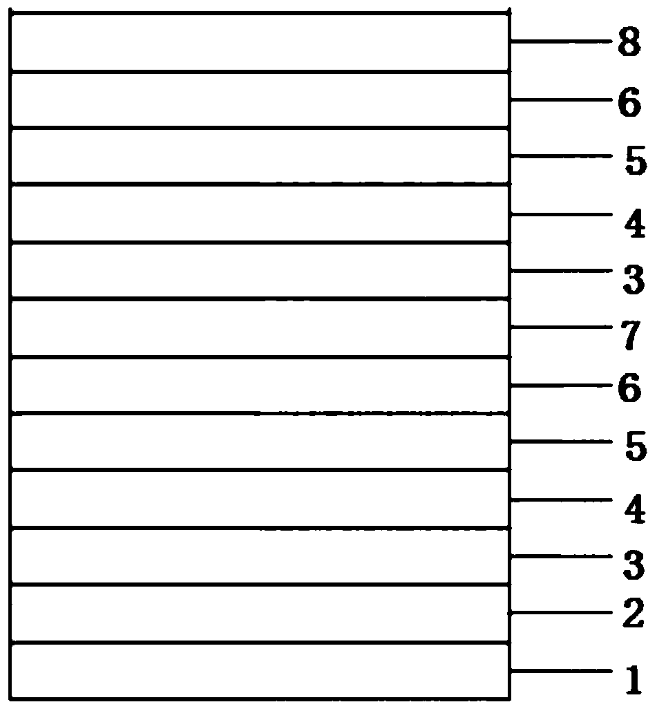
[0059] The structure of the device:

[0060] ITO / HATCN / NPB / Alq3 / Bphen(20nm) / x%Ag:Bphen(10nm) / HATCN / NPB / Alq3 / Bphen / Mg:Ag / Ag;

[0061] The first electrode layer 2 (ITO, anode), the hole injection layer 3 (HATCN), the hole transport layer 4 (NPB), the light emitting layer 5 (Alq 3 ), electron transport layer 6 (Bphen), electron generation layer 7 (x%Ag:Bphen), hole injection layer 3 (HATCN), hole transport layer 4 (NPB), light emitting layer 5 (Alq 3 ), electron transport layer 6 (Bphen), second electrode layer 8 (Mg:Ag / Ag)

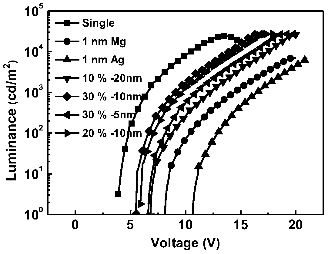
[0062] The host material of the electron generation layer 7 in the present embodiment is Bphen, and the doped inert metal is Ag, such as figure 2 Shown are the voltage-brightness curves from device 1 to device 7, where device 1 is the curve corresponding to single, device 2 is the curve corresponding to 1nm Mg, device 3 is the curve corresponding to 1nm Ag, and device 4 is the curve corresponding to 10%-20nm Device 5 is a curve corresponding to 30%-10nm,...

Embodiment 2

[0075] The structure of device 8 to device 33 is the same as that of device 1, wherein the composition of the electron transport layer and the electron generation layer is as follows:

[0076] Table 1 The composition of electron transport layer and electron generation layer of the present invention

[0077]

[0078]

Embodiment 3

[0080] The structure of device 32 to device 35 is the same as that of device 12, wherein the EMT in the electron transport layer and the electron generation layer adopts the compounds of the structures shown in formula (6-1), formula (6-2) and formula (6-3) respectively , the doped metals M are ruthenium Ru, rhodium Rh and lead Pb respectively, and the doping ratios are 20vol%, 30vol% and 40vol% respectively.


PUM


Abstract

The present invention relates to a laminated organic electroluminescent device, comprising a substrate, and a light-emitting device sequentially formed on the substrate, the light-emitting device comprising a first electrode layer, a hole injection layer, a hole transport layer, and a light-emitting layer , an electron transport layer, an electron generation layer, a hole injection layer, a hole transport layer, a light emitting layer and an electron transport layer second electrode layer, the electron generation layer includes an electron transport material with coordination ability and doped in the Inert transition metals in electron transport materials; electron transport materials with coordination ability can form complexes with inert metal ions to reduce the work function of inert metals, so that they can achieve n-type doping effects similar to active metals and improve free current carrying Subconcentration, reduce the LUMO energy level of the electron transport material, used as the electron generation layer of the laminated device, promote the generation of electrons and enhance the separation of electrons, so that the driving voltage of the device can be significantly reduced, and the device efficiency can be improved.

Description

technical field [0001] The invention relates to the technical field of laminated organic electroluminescent devices, in particular to a laminated organic electroluminescent device in which an electron transport layer with coordination ability is doped with an inert metal to achieve n-type doping effect. Background technique [0002] The stacked organic light-emitting device structure includes a plurality of light-emitting units, and different light-emitting units are stacked through a charge generation layer, and the charge generation layer transports electrons or holes to adjacent light-emitting units. This structure can significantly improve the performance of the device, effectively reduce the phenomenon of current quenching, and improve the working time of the device. [0003] In stacked devices, to achieve a good charge separation effect, n-type dopants are usually used to co-dope with electron transport materials to increase the free carrier concentration and promote t...

Claims


Application Information

Patent Timeline
Patent Type & Authority Patents(China)
IPC IPC(8): H01L51/50H01L51/52H01L51/54
CPCH10K85/30H10K50/15H10K50/165H10K50/16
Inventor 段炼宾正杨
Owner TSINGHUA UNIV
Why Eureka
Try Eureka