Method for avoiding die-bonding electric leakage of flip chip

A flip-chip and crystal-bonding technology, which is applied to circuits, electrical components, and electrical solid devices, can solve problems such as insufficient chip adhesion, high porosity, and short circuits, so as to improve quality and yield, and avoid sticking Insufficient relay, avoiding the effect of increasing the porosity rate

Inactive Publication Date: 2017-12-12
合肥彩虹蓝光科技有限公司
View PDF10 Cites 9 Cited by
  • Summary
  • Abstract
  • Description
  • Claims
  • Application Information

AI Technical Summary

Problems solved by technology

The amount of conductive silver glue requires a high amount of glue. Too much glue may cause leakage or even short circuit, while too little glue may lead to insufficient adhesion of the chip and increased porosity.

Method used

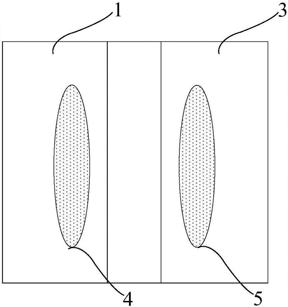
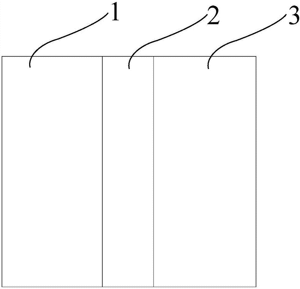

Image

  • Method for avoiding die-bonding electric leakage of flip chip
  • Method for avoiding die-bonding electric leakage of flip chip
  • Method for avoiding die-bonding electric leakage of flip chip

Examples


Embodiment Construction

[0040] Embodiments of the present invention are described below through specific examples, and those skilled in the art can easily understand other advantages and effects of the present invention from the content disclosed in this specification. The present invention can also be implemented or applied through other different specific implementation modes, and various modifications or changes can be made to the details in this specification based on different viewpoints and applications without departing from the spirit of the present invention.

[0041] see Figure 2 to Figure 9 , It should be noted that the diagrams provided in this embodiment are only schematically illustrating the basic idea of ​​the present invention, and only the components related to the present invention are shown in the diagrams rather than the number and shape of components in actual implementation. and size drawing, the type, quantity and proportion of each component can be changed arbitrarily during...


PUM


Abstract

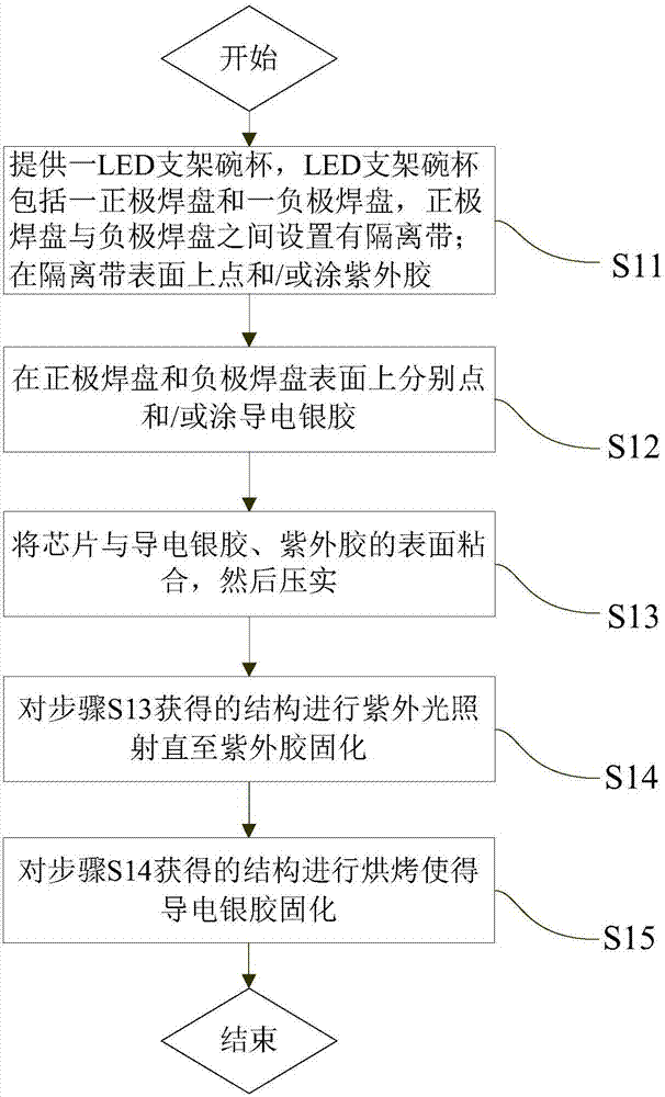
The invention provides a method for avoiding die-bonding electric leakage of a flip chip. The method comprises the following steps of S11, providing an LED bracket bowl cup, wherein the LED bracket bowl cup comprises a positive electrode bonding pad and a negative electrode bonding pad, and an isolation band is placed between the positive electrode bonding pad and the negative electrode bonding pad; and dispensing and/or coating the surface of the isolation band with ultraviolet adhesive; S12, dispensing and/or coating the surfaces of the positive electrode bonding pad and the negative electrode bonding pad with conductive silver adhesive separately; S13, enabling the chip to be glued with the surfaces of the conductive silver adhesive and the ultraviolet adhesive, and then performing tight compression; S14, performing ultraviolet irradiation on the structure obtained in the step S13; and S15, performing baking of the structure obtained in the step S14. By setting the ultraviolet adhesive between the conductive silver adhesive on the surfaces of the positive electrode bonding pad and the negative electrode bonding pad, contact between the two parts of the conductive silver adhesive is blocked, thereby further avoiding the possibilities of electric leakage or even short circuit caused by die bonding; and by adoption of the ultraviolet adhesive for gluing the chip, the problems of insufficient adhesive force of the chip and increased hole rate can be avoided.

Description

technical field [0001] The invention relates to the technical field of LED flip chip bonding, in particular to a method for avoiding leakage of flip chip bonding. Background technique [0002] As the power of LED products will become larger and larger, the ensuing heat dissipation problem will become more prominent. The heat dissipation of wire-bonded full-mount LED products will become the most important problem under the condition of high current. At the same time, because the front electrode faces upward, it will block part of the light and reduce the luminous efficiency. The flip-chip technology can be compared with the traditional packaging technology. Get more effective light output and better heat dissipation. [0003] At present, the chip flip-chip welding methods in the LED industry mainly include flip-chip eutectic soldering, flip-chip solder paste, and conductive silver glue soldering. [0004] Flip-chip eutectic soldering means that when the LED chip adopts eut...

Claims


Application Information

Patent Timeline
Patent Type & Authority Applications(China)
IPC IPC(8): H01L33/62
CPCH01L33/62H01L24/83H01L2933/0066
Inventor 李华楠潘尧波关承浩王党杰
Owner 合肥彩虹蓝光科技有限公司
Why Eureka
Try Eureka