
Regeneration Control System of Particulate Filter Based on CAN Communication

A particulate filter and CAN communication technology, which is applied in the field of particulate filter regeneration control system, can solve the problems of restriction, particulate matter cannot be ignited, and diesel oil cannot be oxidized to achieve temperature rise, so as to increase exhaust temperature and avoid high temperature impact damage effect

Inactive Publication Date: 2020-06-19
WUHAN UNIV OF TECH
View PDF7 Cites 0 Cited by
  • Summary
  • Abstract
  • Description
  • Claims
  • Application Information

AI Technical Summary

Problems solved by technology

However, relying solely on pre-engine treatment and internal purification technology can no longer meet the increasingly stringent emission regulations, and the after-treatment technology of diesel engines is particularly important.
DPF is the most effective and widely used method to deal with exhaust particulate matter, but its regeneration control technology is relatively backward. Faced with this situation, DPF technology is restricted
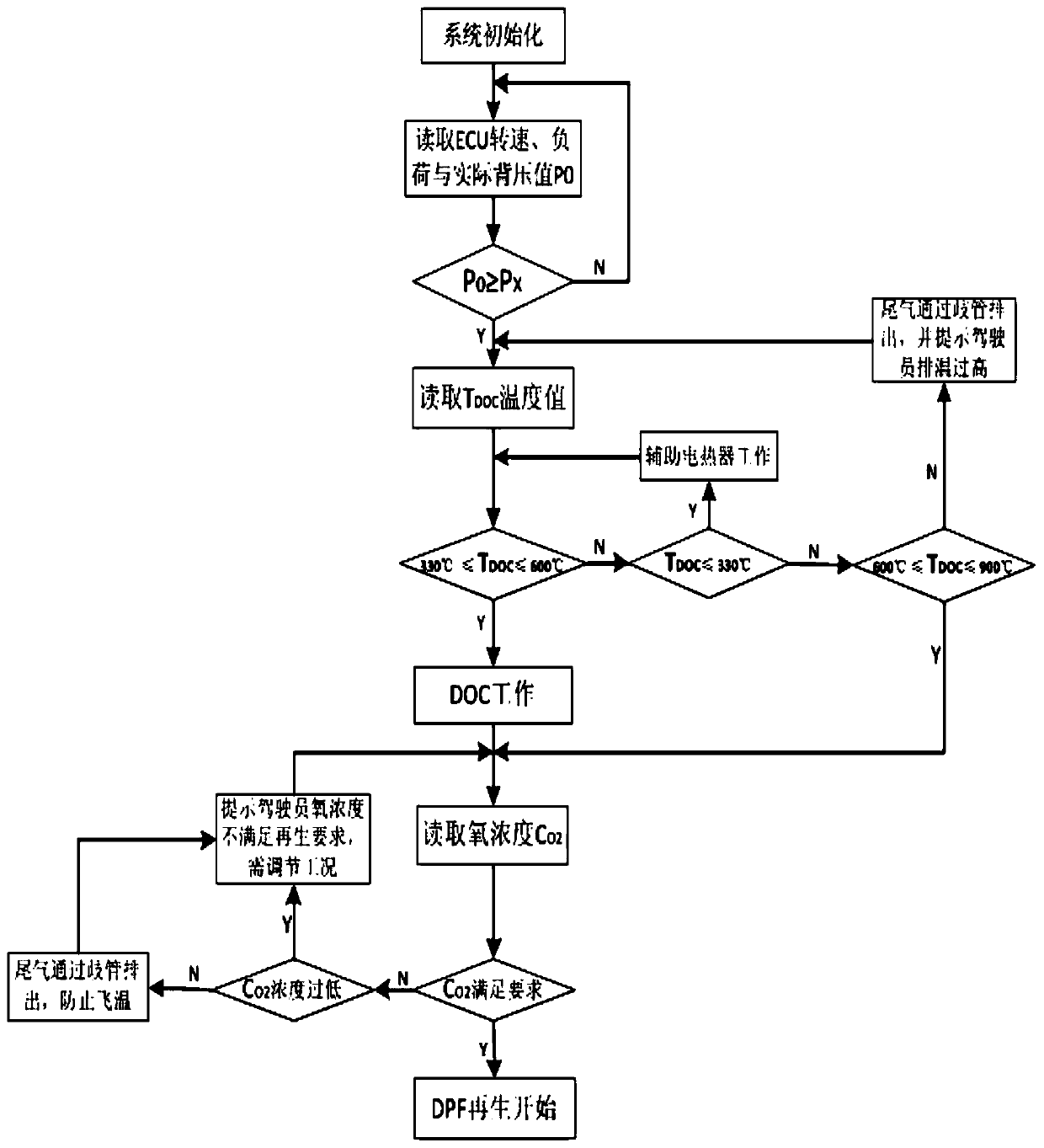
[0003] At present, more regeneration methods are used to realize the active regeneration of DPF through DOC+DPF, but when the temperature of DOC is lower than 330°C, it cannot oxidize the injected diesel oil to achieve the purpose of temperature rise; the temperature inside DPF is lower than 600°C At this time, the particles cannot be ignited to achieve the purpose of regeneration. When the temperature is higher than 1000 ° C, the DPF will be irreversibly damaged due to high temperature, so it is particularly important to control the regeneration temperature of the system

Method used


Image

  • Regeneration Control System of Particulate Filter Based on CAN Communication
  • Regeneration Control System of Particulate Filter Based on CAN Communication
  • Regeneration Control System of Particulate Filter Based on CAN Communication

Examples


Embodiment Construction

[0020] In order to have a clearer understanding of the technical features, purposes and effects of the present invention, the specific implementation manners of the present invention will now be described in detail with reference to the accompanying drawings.

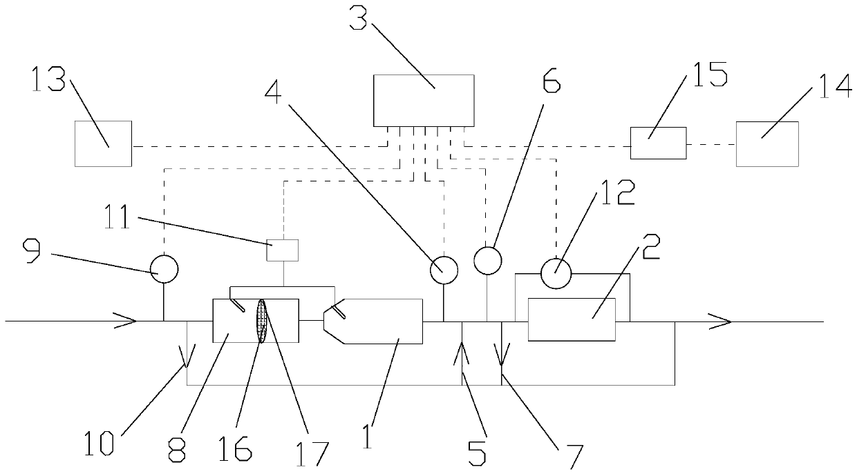
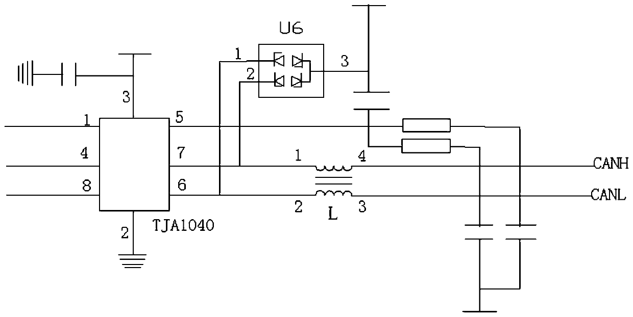
[0021] like Figure 1-3 As shown, the CAN communication-based particulate filter regeneration control system of the present invention includes a catalytic oxidizer DOCl, a particulate filter DPF2, and a regeneration control unit DCU3.

[0022] The second temperature sensor 4, the second exhaust manifold 5, the oxygen sensor 6 and the third exhaust manifold 7 are connected in series between the catalytic oxidizer DOC1 and the particle filter DPF2, and the inlet port of the catalytic oxidizer DOC1 is connected in series with the first A temperature sensor 9, a first exhaust manifold 10 and an auxiliary electric heater 8, the auxiliary electric heater 8 is connected to the diesel injection metering unit 11, the catalytic o...


PUM


Abstract

The invention relates to a diesel particulate filter regeneration control system based on CAN communication. The diesel particulate filter regeneration control system comprises a catalytic oxidizer DOC, a diesel particulate filter DPF and a regeneration control unit DCU; the inlet end of the catalytic oxidizer DOC is provided with an auxiliary electric heater, and the other end of the auxiliary electric heater is sequentially provided with a first temperature sensor and a first exhaust manifold; a second temperature sensor, a second exhaust manifold, an oxygen sensor and a third exhaust manifold are sequentially connected between the catalytic oxidizer DOC and the diesel particulate filter in series, the auxiliary electric heater and the catalytic oxidizer DOC are connected with a diesel injection metering unit, and a differential pressure sensor and the diesel particulate filter are connected in parallel. According to the diesel particulate filter regeneration control system based on CAN communication, through an auxiliary electric heating and oil injection combustion-supporting combined treatment method, full-work-condition regeneration of the diesel particulate filter is achieved, and the condition that the DPF device is burnt due to high temperature can be effectively prevented.

Description

technical field [0001] The invention relates to a particle trap regeneration control system, more specifically, to a particle trap regeneration control system based on CAN communication. Background technique [0002] In recent years, most parts of my country have been seriously threatened by smog. Diesel engine emissions are an important source of PM, and its treatment has attracted more and more attention. However, only relying on pre-engine treatment and internal purification technology can no longer meet the increasingly stringent emission regulations, so the after-treatment technology of diesel engines is particularly important. DPF is the most effective and widely used method to deal with exhaust particulate matter, but its regeneration control technology is relatively backward. Faced with this situation, DPF technology is restricted. [0003] At present, more regeneration methods are used to realize the active regeneration of DPF through DOC+DPF, but when the temperat...

Claims


Application Information

Patent Timeline
Patent Type & Authority Patents(China)
IPC IPC(8): F01N9/00F01N3/027F01N3/025
CPCF01N3/0253F01N3/027F01N9/002Y02T10/40
Inventor 商蕾徐浦星杨亚磊舒飞
Owner WUHAN UNIV OF TECH
Learn More