Eureka AIR delivers breakthrough ideas for toughest innovation challenges, trusted by R&D personnel around the world.

Adjustable embroidery stand

An adjustable and embroidery technology, applied in the field of embroidery, can solve the problems of embroidery deviation, fixing of the mounting plate, affecting the beauty of the finished embroidery, etc., and achieves the effect of simple structure and convenient operation.

Pending Publication Date: 2017-12-12
贵州绣之魂民族服饰有限公司
View PDF9 Cites 9 Cited by
  • Summary
  • Abstract
  • Description
  • Claims
  • Application Information

AI Technical Summary

Problems solved by technology

[0002] Embroidery technology has been passed down in China for a long time. Although many large-scale mechanized embroidery equipments have greatly improved the productivity of embroidery products, traditional hand embroidery has incomparable delicacy and is widely loved by people. In the process of traditional hand embroidery, usually Embroidery frames are needed. Spreading the embroidered cloth is beneficial to the operation and ensures the embroidery quality. Usually, the embroidery frames used are simple in structure and cannot adapt to various embroidered cloths of different sizes. At the same time, when the user turns the mounting plate to the Angle, it is impossible to fix the mounting plate at this angle, resulting in embroidery deviation during the embroidery process and affecting the aesthetics of the finished embroidery; therefore, we propose an adjustable embroidery bracket to solve the above problems

Method used


Image

  • Adjustable embroidery stand
  • Adjustable embroidery stand

Examples


Embodiment Construction

[0013] The following will clearly and completely describe the technical solutions in the embodiments of the present invention with reference to the accompanying drawings in the embodiments of the present invention. Obviously, the described embodiments are only some, not all, embodiments of the present invention.

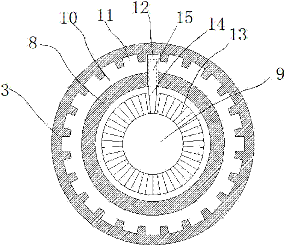
[0014] refer to Figure 1-2 , an adjustable embroidery support, including two bases 1 arranged parallel to each other, the upper surface of the base 1 is provided with a support 2 perpendicular to the base 1, and the side wall of the end of the support 2 away from the base 1 is rotated by a rotating shaft 8 The mounting plate 3 is connected, and the bracket 2 adopts a telescopic structure, and a locking device is provided at the telescopic part. The height of the bracket 2 can be adjusted by adjusting the locking device, so as to adapt to users of various heights. There are two slide bars 4 arranged parallel to each other, and the side of the mounting plate 3 away fr...


PUM


Abstract

The invention discloses an adjustable embroidery stand, comprising two bases which are parallel to each other; the upper surfaces of the bases are respectively provided with a support, and the two supports are respectively vertical to the bases; the side walls of the ends, far away from the bases, of the supports are respectively and rotatably connected with a mounting plate by means of a rotating shaft, and two sliding rods which are parallel to each other are arranged between the two mounting plates; sliding grooves are formed at the sides, far away from the rotating shafts, of the mounting plates; the two ends of the sliding rods are respectively inserted into the sliding grooves and are connected with the sliding grooves in a sliding way; strip-shaped openings communicated with the sliding grooves are formed in the upper surfaces of the mounting plates, and locking screws are respectively arranged in the strip-shaped openings and are respectively connected with the sliding rods by screw threads; rotary slots are formed at the sides, close to the rotating shafts, of the mounting plates, and openings of the rotary slots are formed towards the rotating shafts. The adjustable embroidery stand can adapt to various sizes of embroidered cloth; furthermore, not only are the mounting plates conveniently rotated to a proper angle, but the mounting plates can be also fixed at the positions, so that the mounting plates are prevented from shifting during embroidering, and the quality of an embroidery product is enabled not to be influenced.

Description

technical field [0001] The invention relates to the technical field of embroidery, in particular to an adjustable embroidery support. Background technique [0002] Embroidery technology has been passed down in China for a long time. Although many large-scale mechanized embroidery equipments have greatly improved the productivity of embroidery products, traditional hand embroidery has incomparable delicacy and is widely loved by people. In the process of traditional hand embroidery, usually Embroidery frames are needed. Spreading the embroidered cloth is beneficial to the operation and ensures the embroidery quality. Usually, the embroidery frames used are simple in structure and cannot adapt to various embroidered cloths of different sizes. At the same time, when the user turns the mounting plate to the Angle, it is impossible to fix the mounting plate at this angle, resulting in embroidery deviation during the embroidery process and affecting the aesthetics of the finished ...

Claims


Application Information

Patent Timeline
IPC IPC(8): D05C1/02
CPCD05C1/02
Inventor 杨海彬
Owner 贵州绣之魂民族服饰有限公司
Why Eureka
Eureka Blog
Learn More