
Carbon steel structural component self-compression electric arc additive manufacturing method

A technology for additive manufacturing and structural parts, applied in the field of additive manufacturing, can solve the problems of large wall thickness of titanium alloy structural parts, decreased mechanical properties of components, complex additive manufacturing methods, etc., and achieves good arc stability and low equipment cost. , the effect of high-precision and high-efficiency additive manufacturing

Active Publication Date: 2017-12-12
NANJING UNIV OF SCI & TECH
View PDF7 Cites 9 Cited by
  • Summary
  • Abstract
  • Description
  • Claims
  • Application Information

AI Technical Summary

Benefits of technology

This new technology allows for better control during formation of carbon steels structures by creating them through direct addition techniques like CNC machining without requiring expensive tools such as lasers or other methods that require an external source of power. It also improves upon current processes used for producing these types of materials due to its ability to achieve precise dimensions while maintaining their strength characteristics at room temperature. Additionally, it simplifies the structure making up process compared to previous methods which required multiple steps before final assembly. Overall, this innovation makes possible more economically viable ways to produce complex carbon steel products on demand than previously available options.

Problems solved by technology

This patents discuss how current techniques have limitations such as slow process times or expensive materials usage due to excessive energy consumption during machining operations. Additionally, existing methods require multiple steps involving different types of tools, leading to increased costs associated with producing these structures.

Method used

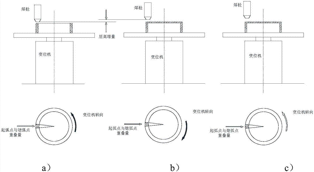
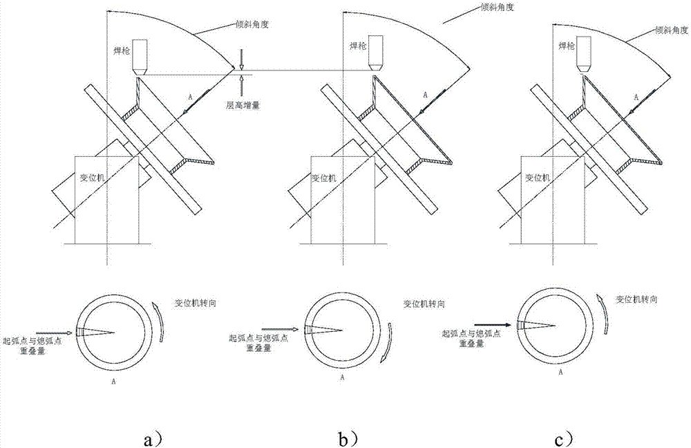

Image

  • Carbon steel structural component self-compression electric arc additive manufacturing method
  • Carbon steel structural component self-compression electric arc additive manufacturing method
  • Carbon steel structural component self-compression electric arc additive manufacturing method

Examples


Embodiment Construction

[0025] A self-compression arc additive manufacturing method for carbon steel structural parts according to the present invention will be further described below in conjunction with the accompanying drawings and specific embodiments.

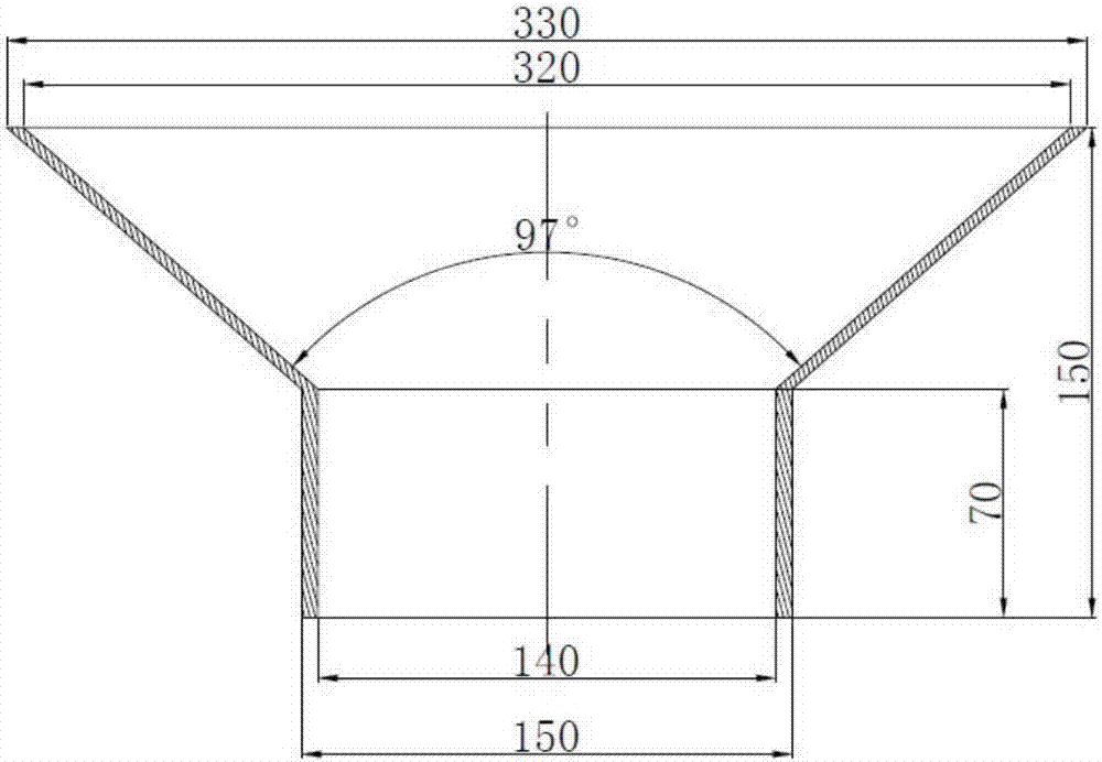
[0026] like image 3 As shown, the carbon steel structural member consists of two parts: a cylindrical shell and a conical shell. Among them, the cylindrical shell part has a height of 70mm and a wall thickness of 5mm, which is composed of 140 layers of stacked metal sheets, each sheet height is 0.35mm; the height of the conical part is 80mm, the wall thickness is 5mm, and the cone angle is 97 °, consisting of 220 layers of stacked metal sheets.

[0027] Process: The stacking current is 120A, the stacking speed is 40cm / min, the wire filling speed is 0.8 / min, the ion gas is 0.8L / min, the protective gas is 15L / min, the wire material is Ф1mm H08Mn2Si, and the stacking layer width is 5mm .

[0028] Equipment used: arc additive manufacturing platfo...


PUM

PropertyMeasurementUnit
Widthaaaaaaaaaa

Abstract

The invention provides a carbon steel structural component self-compression electric arc additive manufacturing method which comprises the following steps: independent wire filling is cooperated with the self-compression electric arc additive manufacturing method to carry out layered overlaying weld forming on a revolving part, that is, a wire feeding mechanism fills wires; self-compression electric arc serves as a heat source to melt the wires so as to carry out overlaying weld forming; and the vertical movement of a welding gun and the turnover and rotating motion of a deflection machine are utilized to form an overlaying weld path, so that the overlaying weld process of the structure-variable revolving part is always vertical revolving part. The welding gun moves by a fixed height in the vertical direction when a layer is subjected to overlaying weld, the overlaying weld manner is repeated to form a next annular overlaying weld layer, and finally, the annular overlaying weld layers are accumulated and overlapped to form the carbon steel structural component with special geometrical characteristics through reciprocating circulation. The structural component is stable in overlaying weld forming process; and a formed component is high in density and mechanical property, reaches or excesses the traditional combined process component manufacturing level of the component made of the same-component material, is high in forming precision and material utilization ratio, is simplified in manufacturing process, and is high in metal deposition velocity and production efficiency.

Description


Claims


Application Information

Patent Timeline
Owner NANJING UNIV OF SCI & TECH
Learn More