Antenna device of step frequency continuous wave through wall radar

A stepped frequency continuous wave, wall-penetrating radar technology, applied in independent non-interaction antenna combination, antenna, antenna coupling and other directions, can solve the problems of receiver saturation, low isolation, and lower radar performance, and reduce interaction Effects of coupling factor, improved isolation, and low sidelobe level

Active Publication Date: 2017-12-05
HUNAN NOVASKY ELECTRONICS TECH
View PDF14 Cites 3 Cited by
  • Summary
  • Abstract
  • Description
  • Claims
  • Application Information

AI Technical Summary

Problems solved by technology

[0003] If the number of antenna elements in the through-wall radar antenna device is small, the number of channels cannot meet the needs of rapid energy accumulation, etc., and the actual sensitivity and azimuth resolution of the radar will be reduced accordingly, which will not be able to meet the actual two-dimensional positioning and multi-dimensional positioning. Target detection requirements; the isolation between the transmitting and receiving antennas is the key to the stepping frequency continuous wave system radar to achieve long-range detection and high-precision detection, etc. Therefore, for the through-wall radar antenna device, it is necessary to meet the requirements of multiple elements of the continuous wave radar antenna device , it is also necessary to solve the isolation problem between the transceiver antennas, and at the same time meet the requirements of radar miniaturization. If the isolation between the transceiver antennas cannot meet the system requirements, the energy leakage of the radar transmitter will directly affect the sensitivity and dynamic range of the receiver. At the same time shorten the range of radar action, reduce radar performance, and may even cause receiver saturation, making it impossible to track and detect targets
[0004] For the antenna device in the existing wall-penetrating radar with stepped frequency continuous wave system, when the impedance bandwidth remains constant, the aperture size of the antenna device is distributed in proportion to the number of array elements, that is, the larger the aperture size, the corresponding array element The greater the number, when the aperture size of the antenna device is constant, the number of elements in the antenna device and the isolation between the transceiver antennas are inversely proportional to the distribution, that is, the more the number of array elements, the lower the isolation between the corresponding transceiver antennas , it is very difficult to make the antenna device achieve a sufficiently small radiation aperture and a sufficient number of array elements, and at the same time make the isolation between the transmitting and receiving antennas large enough. Antenna device, it is actually difficult to meet the requirements of multi-array elements of radar antenna device and the isolation between transmitting and receiving antennas at the same time

Method used


Image

  • Antenna device of step frequency continuous wave through wall radar
  • Antenna device of step frequency continuous wave through wall radar
  • Antenna device of step frequency continuous wave through wall radar

Examples


Embodiment Construction

[0032] The present invention will be further described below with reference to the accompanying drawings and specific preferred embodiments, but the protection scope of the present invention is not limited thereby.

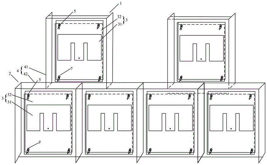
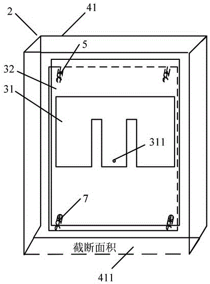
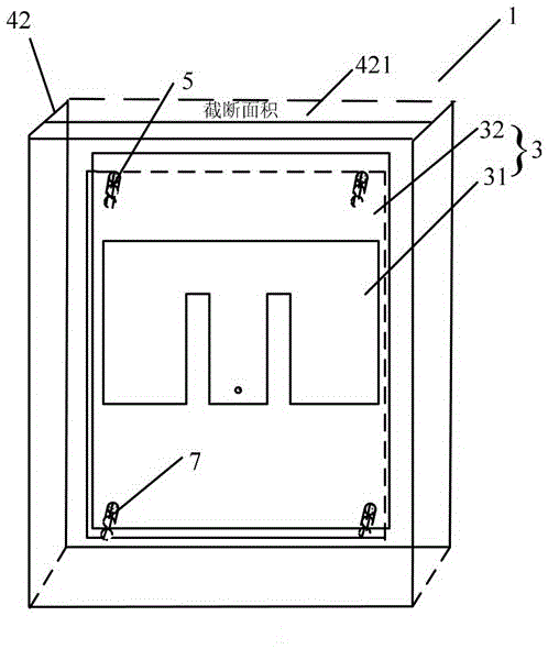
[0033] like Figures 1 to 3 As shown, the antenna device of the stepped frequency continuous wave through-wall radar in this embodiment specifically includes more than two groups (specifically, two groups) of transmitting antennas 1 for transmitting radar signals, and multiple groups (specifically, four groups) for receiving radar signals. The echo receiving antenna 2, the transmitting antenna 1 and the receiving antenna 2 are arranged in parallel on the upper and lower layers of the radar radiation surface, respectively. The structures of each group of transmitting antennas 1 and 2 are the same. The antenna radiation unit 3 and the reflection back cavity 4, the antenna radiation unit 3 is arranged in the reflection back cavity 4, and the reflection back cavity 4 ...


PUM


Abstract

The invention discloses an antenna device of a step frequency continuous wave through wall radar. The antenna device comprises more than two groups of transmitting antennas used for transmitting radar signals and a plurality of groups of receiving antennas used for receiving radar echoes. The transmitting antennas and the receiving antennas are respectively and parallely disposed on an upper layer and a lower layer of a radar radiation surface. Every group of transmitting antennas and every group of receiving antennas comprise antenna radiation units and reflection back cavities, and the antenna radiation units are disposed in the reflection back cavities. Every reflection back cavity has a rectangular chamber structure enclosed by five surfaces, and one of the surfaces is a defective surface having a partial cross section area. The antenna device is advantageous in that a structure is simple, and required costs are low, and in addition, multi-element is realized, and at the same time, a degree of isolation between the transmitting antennas and the receiving antennas is high, and the adjustment of the isolation degree is flexible, and gain is high.

Description

technical field [0001] The invention relates to the technical field of stepped frequency continuous wave radar, in particular to an antenna device of a stepped frequency continuous wave through-wall radar. Background technique [0002] Through-wall radar is a typical system for detecting and positioning targets in non-transparent medium (except metal) barriers, and can detect, locate, track and image moving and stationary targets behind walls; stepped frequency continuous wave radar has high orientation accuracy , good penetration, strong anti-interference ability and strong target separation ability. Stepped frequency continuous wave through-wall radar is the application of stepped frequency continuous wave radar in through-wall radar, through the transmitting antenna to transmit high-frequency electromagnetic waves, and then through the receiving antenna to receive the target reflected echo, so as to pass the LNA, high-pass filter, Automatic gain amplification, frequency ...

Claims


Application Information

Patent Timeline
Patent Type & Authority Applications(China)
IPC IPC(8): H01Q1/52H01Q15/18H01Q19/10H01Q19/12H01Q21/00H01Q21/28
CPCH01Q1/525H01Q15/18H01Q19/106H01Q19/12H01Q21/00H01Q21/28Y02A90/10
Inventor 蔡彬王博韩明华
Owner HUNAN NOVASKY ELECTRONICS TECH
Why Eureka
Try Eureka