
Reinforcing device for high-span portion of combined framework

A reinforcement device and high-span technology, applied in building construction, building maintenance, industrial buildings, etc., can solve problems such as hidden dangers in the operation of substation structures, and achieve the effects of enhancing overall rigidity, convenient and flexible use, and eliminating displacement.

Pending Publication Date: 2017-12-05
STATE GRID JIANGSU ECONOMIC RES INST +2
View PDF5 Cites 1 Cited by
  • Summary
  • Abstract
  • Description
  • Claims
  • Application Information

AI Technical Summary

Problems solved by technology

This method requires bevel welding on the original steel pipe, so it is suitable for the situation that the steel pipes of high-span columns and low-span beams are both thick. If the steel pipe wall thickness is thin or the steel pipe outlet is corroded, etc., this method It is easy to damage the original structural rods, causing safety hazards to the operation of the substation structure

Method used


Image

  • Reinforcing device for high-span portion of combined framework
  • Reinforcing device for high-span portion of combined framework
  • Reinforcing device for high-span portion of combined framework

Examples


Embodiment 1

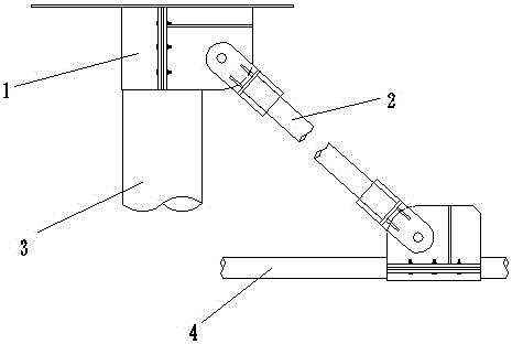
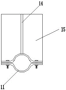
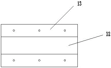
[0026] The combined frame includes a low-span part and a high-span part, the high-span part is arranged above the low-span part, the high-span part is provided with a high-span column, and the low-span part is provided with a low-span beam. The high-span part of the combined frame of this embodiment The reinforcement device is set on the high-span columns and low-span beams connected to each other in the joint frame. The structure is as follows: figure 1 As shown, it includes two hoops 1 and a connecting rod 2 between the two hoops 1, the two ends of the connecting rod 2 are respectively hinged with the two hoops 1, and the two hoops 1 are detachably fixed on the high On the span column 3 and the low span beam 4.

[0027] Such as figure 2 , 3 As shown in and 4, the hoop 1 includes two hoop bodies 11 that are symmetrical to each other. The hoop body 11 includes an arc cylindrical hoop portion 12 and fixing portions 13 located at both ends of the hoop portion. The fixing port...

Embodiment 2

[0035] The structure of the reinforcement device in this embodiment is basically the same as that of Embodiment 1, the difference is that the middle part of the connecting rod 2 in this embodiment is a high-strength spring, which allows the connecting rod to have a certain length adjustment range during use, and can adjust the length of the connecting rod. The horizontal force on the high-span part of the joint frame plays a certain buffering role.


PUM


Abstract

The invention relates to a reinforcing device for a high-span portion of a combined framework, and the reinforcing device is arranged on a high-span column and a low-span beam of the combined framework. The reinforcing device comprises two hoops and a connecting bar located between the two hoops. The two ends of the connecting bar are hinged to the two hooks correspondingly. The two hoops are detachably fixed to the high-span column and the low-span beam correspondingly. The reinforcing device provided by the invention is obliquely supported between the high-span column and the low-span beam and can effectively reinforce the high-span structure.

Description

technical field [0001] The invention relates to a reinforcing device for a combined structure, in particular to a reinforcing device for a high-span part, and belongs to the technical field of substation equipment accessories. Background technique [0002] The substation structure is the most important structure of the substation. The substation structure has high importance, heavy load, high economic index and complex process requirements. The joint frame is generally used in the power distribution site with a higher voltage level, and the high-span part is often designed in the form of a single pole. With the passage of time, the aging phenomenon of the single-pole column will inevitably occur, and the strength will also decrease accordingly; at the same time, the bending strength of the single-pole column is limited, and the tension of the wire often becomes larger than the original during the technical transformation of the substation. Architectural design conditions. ...

Claims


Application Information

Patent Timeline
Patent Type & Authority Applications(China)
IPC IPC(8): E04G23/02E04H5/04
CPCE04G23/0218E04H5/04
Inventor 储方舟李杰丁静鹄
Owner STATE GRID JIANGSU ECONOMIC RES INST
Learn More