
Inductor and protection circuit

A technology for protecting circuits and inductors, which is applied in the direction of transformer/inductor circuits, inductors, emergency protection circuit devices, etc., which can solve the problems of inability to protect devices and time required, and achieve the effect of high magnetic permeability and high inductance

Inactive Publication Date: 2017-12-01
NTN CORP
View PDF9 Cites 0 Cited by
  • Summary
  • Abstract
  • Description
  • Claims
  • Application Information

AI Technical Summary

Problems solved by technology

Therefore, when a circuit breaker or relay is used for a short circuit, it may take more time to cut off than a fuse, and a large short-circuit current may flow to the circuit to be protected, failing to protect the device, etc.

Method used


Image

  • Inductor and protection circuit
  • Inductor and protection circuit
  • Inductor and protection circuit

Examples


Embodiment 1

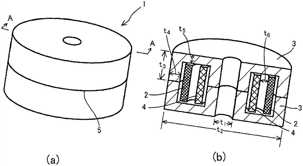
[0066] Use the iron powder particle ( Produced by the company, Somaloy: Insulating coating treatment iron powder) to produce figure 1The illustrated POT-type magnetic core 3 has a space portion in which a coil can be arranged. The size of the magnetic core 3 is the inner diameter (t 1 )28mm, outer diameter (t 2 )120mm, height (t 3 )36.5mm, the lateral thickness of the space part (t 4 ) 12mm, longitudinal thickness of space part (t 5 ) 10mm POT type, make two of them.

[0067] Prepare a rectangular insulated winding with a width and thickness of 5×4.5 mm, and wind it upright to produce a coil with an inner diameter of 80 mm, an outer diameter of 90 mm, and a height of 50 mm. The coil is arranged on one side of the magnetic core 3, and the lead-out wire is fixed.

[0068] On the other hand, use the above-mentioned rectangular insulated winding to make a coil with an inner diameter of 54 mm, an outer diameter of 64 mm, a height of 50 mm, and a coil ratio of 10:1 between t...

Embodiment 2

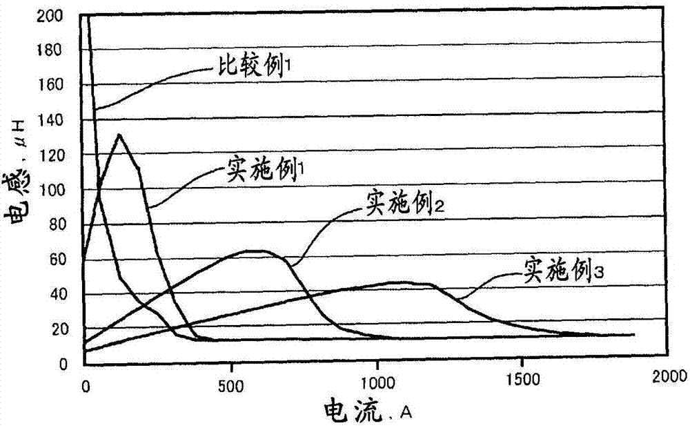
[0071] An inductor similar to Example 1 was produced except that the turn ratio of the coil having the lead wire and the short-circuit coil was 10:3. Inductance was measured by the same method as in Example 1. The result is as figure 2 shown.

Embodiment 3

[0073] An inductor similar to that of Example 1 was produced except that the turn ratio of the coil having the lead wire and the short-circuit coil was 10:5. Inductance was measured by the same method as in Example 1. The result is as figure 2 shown.


PUM

PropertyMeasurementUnit
softening pointaaaaaaaaaa
thicknessaaaaaaaaaa
thicknessaaaaaaaaaa

Abstract

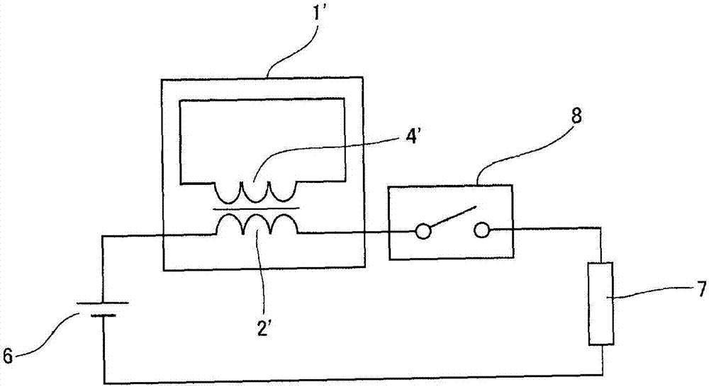
Provided are an inductor with which it is possible to suppress a decrease in inductance without causing magnetic saturation of a magnetic core even under a large current of the order of several 1000 A, such as a surge current, and a protection circuit using the inductor. The inductor comprises an iron-based magnetic core (3) incorporating a main coil (2), with a short-circuited coil (4), in which a coil-winding start is short-circuited to a coil-winding end, disposed in the magnetic core (3) concentrically with the main coil (2), the short-circuited coil having the effect of cancelling out a magnetic field created by an applied current which is applied to the main coil (2), wherein the magnetic core (3) comprises magnetic cores of the same shape which abut one another at an abutting plane (5). The protection circuit comprises a circuit breaker connected between a direct-current power supply and a load, with a current-limiting inductor connected in series with the circuit breaker.

Description

technical field [0001] The present invention relates to inductors and protection circuits, in particular to transformers, reactors, choke coils, filters, sensors and other inductors under high current and high magnetization force and the protection circuit using the inductors. Background technique [0002] In recent years, as the functions of power semiconductors such as switching elements and diodes have improved, the current flowing through circuits has become larger and higher in frequency. Along with this, regarding inductors such as reactors, choke coils, and transformers used in electric circuits, countermeasures against high current and high frequency are required. [0003] In addition, the use of converters for solar power generation and wind power generation, data centers, etc. to handle large currents is also expanding, and countermeasures for these devices against instantaneous large current noise such as lightning called surge currents have become important. [...

Claims


Application Information

Patent Timeline
Patent Type & Authority Applications(China)
IPC IPC(8): H01F37/00H01F27/42
CPCH01F37/00H01F17/043H01F27/38H01F27/42H01F27/24H01F27/28H01F27/402H02H3/025
Inventor 神户祥吾堺香代岛津英一郎小田贵之
Owner NTN CORP
Learn More