Novel dynamic axial compression column pneumatic control structure

A pneumatic control and axial compression technology, which is applied in the direction of fluid pressure actuators, fluid pressure actuator system components, servo motors, etc., can solve the problems of inconvenient operation, laborious switching of cylinder movement direction, and large dynamic axial compression column piston operation Slow speed and other problems, to achieve the effect of increasing flow rate and convenient use

Pending Publication Date: 2017-12-01
JIANGSU HANBON SCI & TECH CO
View PDF5 Cites 1 Cited by
  • Summary
  • Abstract
  • Description
  • Claims
  • Application Information

AI Technical Summary

Problems solved by technology

[0004] In order to solve the above technical problems, the present invention provides a dynamic axial compression column air control structure, the purpose of which is to solve the problems of slow running speed of the piston of the large dynamic axial compression column, laborious switching of the movement direction of the oil cylinder, and inconvenient operation; the specific technical solution as follows:

Method used


Image

  • Novel dynamic axial compression column pneumatic control structure

Examples


Embodiment Construction

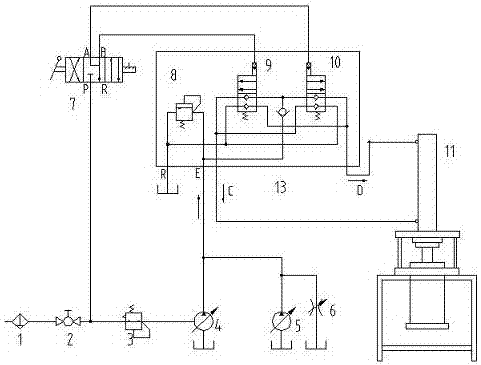
[0015] Combine figure 1 The present invention will be described in further detail. The present invention is composed of a pneumatic control assembly, a hydraulic control assembly, a hydraulic drive assembly and an executive element; the pneumatic control assembly includes an air source switch 2, an air pressure regulating valve 3 and a manual air circuit four-way reversing valve 7. The hydraulic drive assembly It includes a pneumatic hydraulic pump 4, a gear pump 5 and a speed regulating valve 6. The hydraulic control assembly includes a pneumatic control direction switching valve I9, a pneumatic control direction switching valve II10, and an overflow valve 8. The executive component is an oil cylinder 11.

[0016] The gas is filtered by the oil-water separator 1 to remove impurities such as water and oil in the gas path, passes through the gas source switch 2, and reaches the air pressure regulating valve 3. The pressure regulating valve 3 is adjusted to control the output hydra...


PUM


Abstract

The invention discloses a novel dynamic axial compression column pneumatic control structure. The novel dynamic axial compression column pneumatic control structure is composed of a pneumatic control assembly, a hydraulic control assembly, a hydraulic drive assembly and an execution original part; the pneumatic control assembly comprises a gas source switch, a gas pressure adjusting valve and a manual gas path four-way reversing valve; the hydraulic drive assembly comprises a pneumatic hydraulic pump, a gear pump and a speed regulating valve; the hydraulic control assembly comprises a pneumatic control direction switching valve I, a pneumatic control direction switching valve II and an overflow valve; and the execution original part is an oil cylinder. As the gear pump is additionally arranged in the pneumatic control structure, and the filling work of chromatography packing can be finished rapidly; and the pneumatic control structure formed by the pneumatic control direction switching valves and the manual gas path four-way reversing valve is used for switching an output oil path, and the system runs safely, reliably and stably.

Description

Technical field [0001] The invention belongs to the field of preparative chromatography instruments, and specifically relates to a novel dynamic axial compression column gas control structure. Background technique [0002] The dynamic axial compression column system is a new type of equipment for the separation and purification of target substances. It is suitable for the separation and purification of target products in the order of hundred grams and kilograms. It can also be used for small-scale laboratory preparation and process amplification research. It is an industrial preparation The most widely used column in the field. [0003] In the dynamic axial compression column system, the packing of the chromatographic packing is one of the main factors that determine the separation effect of the system. In the traditional small dynamic axial compression column control system, a separate pneumatic hydraulic pump is usually used to drive the movement of the cylinder, hydraulic manual...

Claims


Application Information

Patent Timeline
Patent Type & Authority Applications(China)
IPC IPC(8): F15B21/00F15B21/04F15B13/02F15B11/072F15B11/17
CPCF15B11/0725F15B11/17F15B13/023F15B13/024F15B21/001F15B21/041
Inventor 郑州严忠张大兵沈健增居延娟李枝玲
Owner JIANGSU HANBON SCI & TECH CO
Why Eureka
Try Eureka