
Campus racket automatic leasing machine

A racket, automatic technology for use in instruments, coin-operated equipment for distributing discrete items, coin-free or similar appliances, etc., to solve problems such as machines without rackets

Inactive Publication Date: 2018-12-18
华蓥市观音溪初级中学
View PDF0 Cites 0 Cited by
  • Summary
  • Abstract
  • Description
  • Claims
  • Application Information

AI Technical Summary

Problems solved by technology

[0003] The purpose of the present invention is to provide an automatic rental machine for school rackets, which solves the problem that the prior art does not have a machine specifically for racket rental.

Method used


Image

  • Campus racket automatic leasing machine
  • Campus racket automatic leasing machine

Examples


Embodiment 1

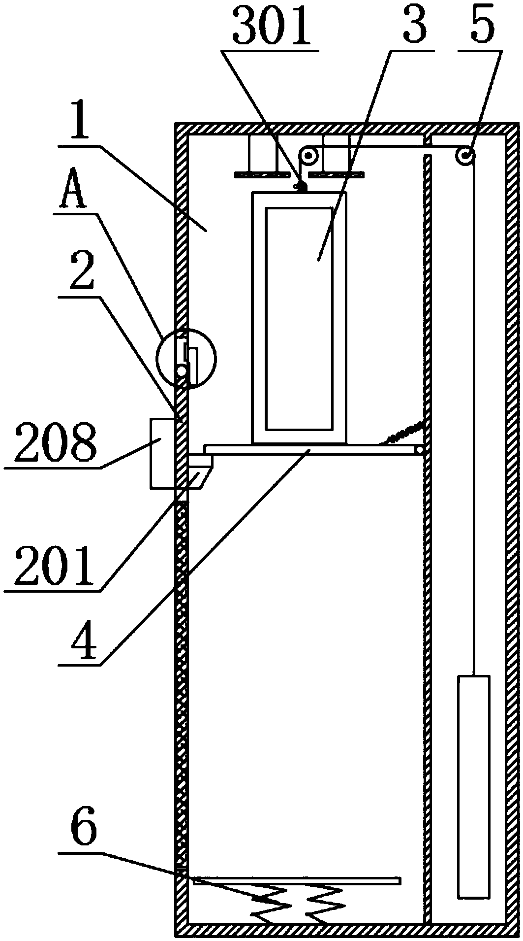
[0023] The automatic school racket rental machine of the present invention includes a body 1 and a racket box 3, and the racket box 3 is arranged in the body 1, and also includes a switch device 2, a baffle plate 4, and a reset device 5, and the switch device 2 is provided with a stopper 201, the baffle 4 is a movable plate, one end is connected to the return spring and the fulcrum, and the other end is placed on the stopper 201, the beat box 3 is placed on the baffle 4 and is located on the upper part of the body 1, and the beat box 3 Connect the reset device 5 for the transfer of the clapper box 3 from the upper part of the body 1 to the lower part, or from the lower part of the body 1 to the upper part; the switch device 2 is arranged on the surface of the body 1 for controlling the stopper 201 Mating or disengaging with the baffle 4. Through the switch device 2 and the reset device 5 in the body 1, the up and down movement of the clapper box 3 is controlled to realize the ...

Embodiment 2

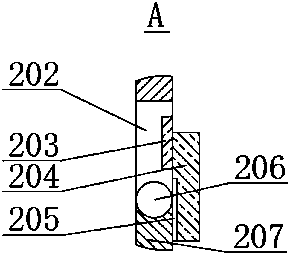
[0025] This embodiment makes the following further limitations on the basis of Embodiment 1: the switch device 2 also includes an inner cavity 202, a control circuit 203, an electromagnet 204205, a magnet 205, a rotating shaft 206, and an action plate 207. The cavity 202 is set between the outer surface and the inner surface of the body 1, the control circuit 203 and the rotating shaft 206 are set in the inner cavity 202, the electromagnet 204205 is controlled by the control circuit 203 to gain and lose power, and the magnet 205 is set to function On the side of the plate 207, cooperate with the electromagnet 204205, and the action plate 207 rotates around the rotating shaft 206 to the inside of the body 1 or outside the body 1. The circuit of the control circuit 203 board is a circuit for controlling the gain and loss of electricity of the electromagnet 204205, which is a commonly used prior art. The control signal input from the outside further controls the power gain and lo...


PUM


Abstract

The invention discloses a campus racket automatic leasing machine. The campus racket automatic leasing machine comprises a machine body, a racket box, a switch device, a baffle and a reset device, wherein the racket box is arranged in the machine body; the switch device is provided with a backstop; the baffle is a movable plate; one end of the baffle is connected with a reset spring and a fulcrum;the other end of the baffle is placed on the backstop; the racket box is placed on the baffle, and positioned on the upper part of the machine body; the racket box is connected with the reset device,and used for transferring the racket box from the inner upper part of the machine body to the lower part, or from the inner lower part of the machine body to the upper part; and the switch device isarranged on the surface of the machine body, and used for controlling the matching or separation of the backstop and the baffle. The function of automatic leasing is realized by controlling the upwardand downward motion of the racket box through the switch device and the reset device in the machine body. Triggering of the falling of the racket box by the switch device is realized through the characteristics of an electromagnet, thereby realizing automatic control during leasing. The transfer function of the reset device for the rising of the racket box is realized through a pulley and a heavyobject, thereby realizing resetting after leasing.

Description

technical field [0001] The invention relates to the field of sporting goods leasing, in particular to an automatic racket leasing machine for campuses. Background technique [0002] With the popularization of campus quality education, more and more students use ball games to strengthen their bodies. However, ball games require corresponding sports equipment, especially sports with rackets, such as badminton, table tennis, Tennis, etc., because high-quality rackets are expensive and not easy to carry around, there is usually a rental service on campus. Because the rackets are all fixed structures, if a special person is set up to manage them, the cost of input will be increased. At the same time, due to the weak connection structure of the racket, especially the badminton racket, it is easy to be damaged after collision. Contents of the invention [0003] The object of the present invention is to provide an automatic racket rental machine for campuses, which solves the pr...

Claims


Application Information

Patent Timeline
Patent Type & Authority Applications(China)
IPC IPC(8): G07F17/00
CPCG07F17/0042
Inventor 陈俊奎常金勇
Owner 华蓥市观音溪初级中学
Learn More