Multifunctional focusing test light box

A multi-function, light box technology, applied in optics, instruments, photography, etc., can solve problems such as low efficiency and inaccuracy, and achieve the effect of improving accuracy, increasing flexibility and accuracy, and improving efficiency and accuracy.

Pending Publication Date: 2022-06-03
深圳市新四季信息技术有限公司
View PDF0 Cites 0 Cited by
  • Summary
  • Abstract
  • Description
  • Claims
  • Application Information

AI Technical Summary

Problems solved by technology

[0002] At present, with the development of electronic technology, the demand for cameras on various electronic products, such as mobile phones and laptop computers, is increasing, and the dependence on image technology is getting higher and higher, and the pixel value of the corresponding cameras is also getting higher and higher. The higher the higher, the higher the resolution of the images taken by the camera is, the more stringent the requirements are. In order to make the optical lens of the camera have an optimal imaging surface, the testers need to adjust the focal lengths of the multiple lenses of the camera in different bands, but now Some equipment generally only have a light box with a single-band (650NM / 850NM / 940NM) light source, which can only meet the focus test of a single lens of the camera, and it is difficult to meet the confocal test of multiple lenses of the camera in different bands at the same time. Switch the focusing equipment of different bands for confocal testing to find the best confocal. This operation is not only inefficient, but also not accurate enough

Method used


Image

  • Multifunctional focusing test light box
  • Multifunctional focusing test light box
  • Multifunctional focusing test light box

Examples


Embodiment Construction

[0028] The following is a further detailed description of the present application.

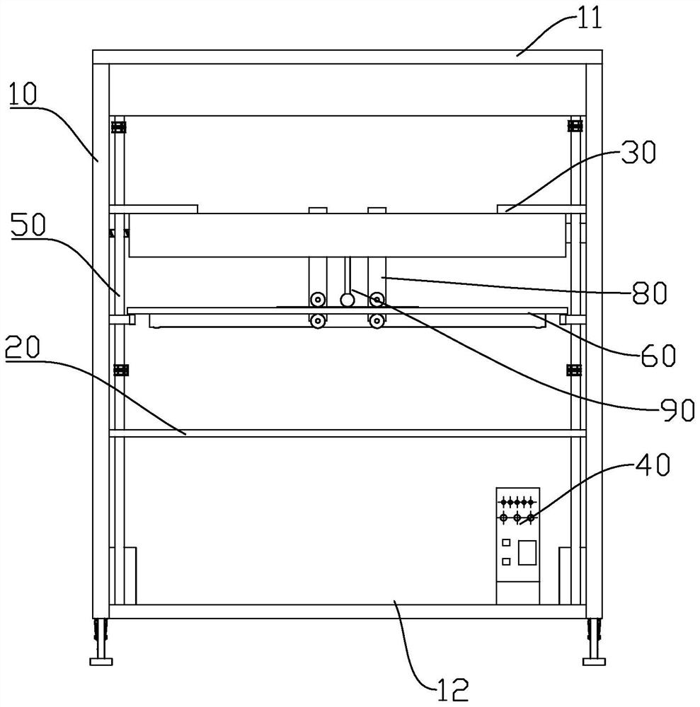
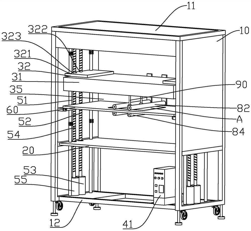
[0029] The embodiment of the present application discloses a multifunctional focusing test light box. see figure 1 and figure 2 , the multi-function focusing test light box includes: a light box frame 10, a substrate 20, a light source module 30, a controller 40 and a light-transmitting component 60. The opposite ends of the light box frame 10 are provided with a top plate 11 and a bottom plate 12, and the substrate 20 is arranged on the Inside the light box frame 10 and located between the top plate 11 and the bottom plate 12, the base plate 20 can be understood as a working platform, which can be used to place electronic equipment for focusing operation, the light source module 30 is arranged in the light box frame 10, and is located on the top plate 11 and the substrate 20 for emitting the test light source.

[0030] The light source assembly 31 includes light source components 313 with...


PUM


Abstract

The invention relates to the technical field of camera focusing equipment, in particular to a multifunctional focusing test light box, which comprises a light box frame, a light box, a light source module, a light source module, a light source module and a light source module, and is characterized in that two opposite ends are provided with a top plate and a bottom plate; the substrate is arranged in the light box frame and is positioned between the top plate and the bottom plate; the light source module is arranged in the light box frame and located between the top plate and the substrate, the light source module comprises a light source assembly, and the light source assembly comprises light source parts with different light wave bands; the light transmitting assembly is arranged in the light box frame and located between the substrate and the light source module; the controller is arranged on the bottom plate and connected with the light source part, and an adjusting assembly for adjusting the light source part is arranged on the controller. The confocal test of the multiple lenses of the camera can be met, and the multi-band confocal test efficiency and the test accuracy of the multiple lenses are improved.

Description

technical field [0001] The application relates to the technical field of camera focusing equipment, in particular to a multifunctional focusing test light box. Background technique [0002] At present, with the development of electronic technology, the demand for various electronic products, such as cameras on mobile phones and notebook computers, is increasing, the dependence on image technology is getting higher and higher, and the pixel value of the corresponding camera is also increasing. In order to make the optical lens of the camera have an optimal imaging surface, the tester needs to adjust the focal length of the multiple lenses of the camera in different bands, but now There are devices that generally only have a light box with a single band (650NM / 850NM / 940NM) light source, which can only meet the focusing test of a single lens of the camera, and it is difficult to meet the confocal test of multiple lenses of the camera in different bands at the same time. Sw...

Claims


Application Information

Patent Timeline
Patent Type & Authority Applications(China)
IPC IPC(8): G03B43/00
CPCG03B43/00
Inventor 付金姣邵尚曾德志
Owner 深圳市新四季信息技术有限公司
Why Eureka
Try Eureka