T-shaped blade root of turbine blade and matched flangeway thereof

A technology for steam turbine blades and flange grooves, which is applied to blade support components, mechanical equipment, engine components, etc., and can solve problems such as high technological requirements for blade roots and flange grooves, affecting the safe operation of blades, and inability to process pin holes, etc. Achieve the effect of good manufacturability, large bearing capacity and compact axial structure

Pending Publication Date: 2017-12-01
HANGZHOU TURBINE POWER GRP
View PDF9 Cites 2 Cited by
  • Summary
  • Abstract
  • Description
  • Claims
  • Application Information

AI Technical Summary

Problems solved by technology

[0008] The problem to be solved by the present invention is: if a T-shaped blade root is used for the medium-height blades on the drum rotor of the reaction steam turbine or the last few stages of low-pressure blades with relatively large centrifugal force, it is easy to make the rounded corners of the blade root and the rounded corners of the rim groove A large stress concentration is generated, which affects the safe operation of the blade; if the double T-shaped blade root is used, although the stress concentration of the blade root fillet and the flange groove fillet is reduced, the blade root and the flange groove require high technology. And the assembly of the final blade is inconvenient; if a fork-shaped blade root is used, pin holes cannot be processed in a limited space except for the final stage and the regulating stage; More axial space is reserved for assembly, and the process requirements are higher

Method used


Image

  • T-shaped blade root of turbine blade and matched flangeway thereof
  • T-shaped blade root of turbine blade and matched flangeway thereof
  • T-shaped blade root of turbine blade and matched flangeway thereof

Examples


Embodiment Construction

[0040] The present invention will be described in detail below in conjunction with accompanying drawing:

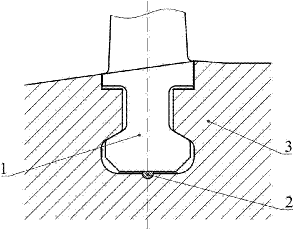
[0041] Such as figure 1 As shown, a T-shaped blade root of a steam turbine blade and its matching rim groove include a steam turbine blade inclined T-shaped blade root 1, a spacer strip 2, and a rim groove 3, the bottom of the inclined T-shaped blade root and the bottom surface of the rim groove Install spacers between them. The oblique T-shaped blade root of the steam turbine blade includes a T-shaped head, a neck, a connecting section between the blade root and the blade body.

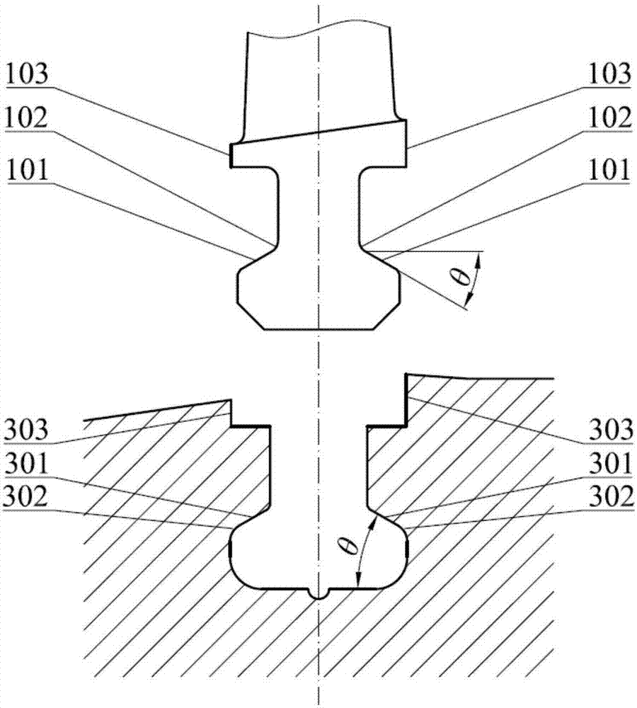
[0042] Such as figure 1 , figure 2 As shown, the oblique T-shaped blade root 1 has an oblique T-shaped head, so the oblique T-shaped head bearing surface 101 and the matching flange groove bearing surface 301 form an included angle θ with the axial direction of the steam turbine. After assembly, the oblique T-shaped blade root 1 is lifted up by the spacer strip 2 at the bottom, so that the ...


PUM


Abstract

The invention relates to a T-shaped blade root of a turbine blade. The T-shaped blade root comprises a T-shaped head part, a neck part, a blade root unit and a blade body connecting section, and is characterized in that observed from a meridian plane section view, a bearing surface, matched with a flangeway, of the T-shaped head part of the blade root is an inclined surface; an included angle theta is formed between the bearing surface of the T-shaped head part of the blade root and the axial direction of a turbine, and an inclined T-shaped head part blade root structure is formed; the bearing surface of the inclined T-shaped head part of the blade root and the neck part of the blade root are in round corner transition; and the value range of the included angle is that delta is larger than or equal to 25 degrees and is smaller than or equal to 30 degrees, and 25 degrees is optimal. Technical defects of a traditional T-shaped blade root are solved, the novel inclined T-shaped blade root of the turbine blade and the matched flangeway thereof are provided, and the novel inclined T-shaped blade root of the turbine blade avoids relatively large stress concentration of a round corner of the T-shaped blade root and a round corner of the flangeway and is relatively high in safety, relatively low in technological difficulty, compact in structure and convenient in assembly.

Description

technical field [0001] The invention relates to a steam turbine moving blade, in particular to a blade root used for a reaction type steam turbine moving blade and a matching wheel rim groove. Background technique [0002] Reaction steam turbines usually use drum rotors. Compared with disk rotors, the materials between the flange grooves of adjacent stages of drum rotors are continuous. Commonly used rotor blade root forms on drum rotors are: T-shaped blade root, double T-shaped blade root, fork-shaped blade root, fir tree-shaped blade root, etc. These types of blade roots mainly have the following characteristics. [0003] T-shaped blade root: simple structure, reliable operation and convenient processing. The blade root is assembled in the circumferential direction, at least one notch must be opened in the rim groove for fixing the blade root, so that the blades can be radially inserted into the rim groove from the notch, and the sealing blade is fixed at the notch positi...

Claims


Application Information

Patent Timeline
Patent Type & Authority Applications(China)
IPC IPC(8): F01D5/30F01D5/03
CPCF01D5/03F01D5/3007
Inventor 庄达明刘象拯王佳男丁旭东
Owner HANGZHOU TURBINE POWER GRP
Why Eureka
Try Eureka