
Systems and methods for ultra-ultra-wide band aesa

A working frequency band and array technology, applied in the field of ultra-ultra-wideband AESA systems and methods, can solve the problems of increasing the complexity and cost of constructing large-scale AESA apertures, not being easy to expand, hindering, etc.

Active Publication Date: 2017-11-28
ROCKWELL COLLINS INC
View PDF4 Cites 5 Cited by
  • Summary
  • Abstract
  • Description
  • Claims
  • Application Information

AI Technical Summary

Problems solved by technology

Furthermore, most existing AESA aperture structures are not easily scalable
This lack of scalability increases the complexity and cost of constructing large AESA apertures
[0003] Limitations of existing AESA systems may prevent the expansion of AESA systems in new communication, military, or sensing systems requiring wider frequency bands than typical UWB supported by existing AESA systems, or requiring large and / or non-planar apertures possibility of using

Method used


Image

  • Systems and methods for ultra-ultra-wide band aesa
  • Systems and methods for ultra-ultra-wide band aesa
  • Systems and methods for ultra-ultra-wide band aesa

Examples


Embodiment Construction

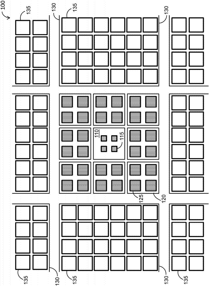
[0016] Before describing the embodiments of the presently disclosed inventive concept in detail, it should be noted that the presently disclosed inventive concept includes but is not limited to novel structural combinations of components and circuits, nor to specific detailed configurations thereof. Accordingly, the structure, method, function, control and arrangement of components and circuits have been shown largely in the drawings by way of easily understandable block diagram representations and schematic diagrams, so as not to obscure the present disclosure with structural details, which are important to It will be apparent to those skilled in the art, having the benefit of the present description. Further, the inventive concepts disclosed herein are not limited to the specific embodiments depicted in the schematic diagrams, but should be construed in accordance with the language of the claims.

[0017] Active electronically scanned array (AESA) antenna systems are used in...


PUM


Abstract

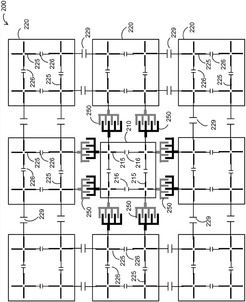
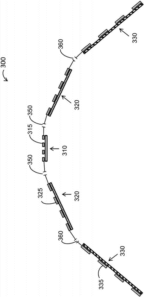
In one aspect, the inventive concepts disclosed herein are directed to an antenna array system employing a current sheet array (CSA) wavelength scaled aperture. The CSA wavelength scaled aperture can include a first frequency region associated with a first operating frequency band and a second frequency region associated with a second operating frequency band. The first operating frequency band can include one or more current sheet sub-arrays having a respective plurality of first unit cells scaled to support the first operating frequency band. The second operating frequency band can include one or more current sheet sub-arrays having a respective plurality of second unit cells scaled to support the second operating frequency band. The CSA wavelength scaled aperture can include one or more capacitors each of which coupled to a respective first unit cell of the first frequency region and a respective second unit cell of the second frequency region.

Description

Background technique [0001] Active electronically scanned array (AESA) systems provide reliable performance over corresponding ultra-widebands (UWBs) of operating frequencies. AESA systems are commonly used in communication systems, military and weather radar systems, electronic intelligence systems, or biological or medical microwave imaging systems. AESA systems utilize arrays of operable radiating elements (or antenna elements) via corresponding sets of transmit / receive modules (TRMs). By steering each of its antenna elements independently, an AESA system provides relatively high reception / transmission performance through the constructive accumulation of signals associated with multiple antenna elements. Additionally, a single failure of one or a few antenna elements within an AESA system has little effect on the operation of the AESA system as a whole due to the inherent ability to simultaneously use and independently steer corresponding multiple antenna elements. Also, ...

Claims


Application Information

Patent Timeline
IPC IPC(8): H01Q1/36H01Q21/06H01Q21/30
CPCH01Q21/30H01Q23/00H01Q1/286H01Q21/062H01Q21/20H01Q3/2682H01Q21/0025
Inventor 詹姆斯·B·韦斯特
Owner ROCKWELL COLLINS INC
Learn More