
Pixel definition layer and preparation method and application thereof

A pixel-defining layer and element technology, applied in semiconductor/solid-state device manufacturing, electrical components, electrical solid-state devices, etc., can solve the problem of poor compatibility, limited baking temperature and time, and difficulty in ensuring phase separation and the same height pinning point etc.

Inactive Publication Date: 2017-11-28
GUANGDONG JUHUA PRINTING DISPLAY TECH CO LTD
View PDF3 Cites 14 Cited by
  • Summary
  • Abstract
  • Description
  • Claims
  • Application Information

AI Technical Summary

Problems solved by technology

[0006] (1) The PI layer has a porous structure. There are pores between the PI polymer chains. Small molecular impurities such as water and solvent molecules can easily enter the pores and be captured or adsorbed. The subsequent baking process of the organic film layer is often baked to avoid damage to the organic matter. Baking temperature and time are limited, so it is difficult to completely remove small molecular impurities in the porous structure of the bank
These small molecular impurities may slowly seep out after the electroluminescent device is fabricated, which will easily reduce the performance and life of the device
[0007] (2) The PI material is transparent to visible light, and the light emitted by a single pixel may pass through the bank and enter adjacent pixels, resulting in crosstalk of the luminous signal and a decrease in the contrast of the display
[0008] (3) The PI type bank needs to rely on the heating program to control the phase separation. This method is difficult to ensure that each area of ​​the large-area bank layer has a consistent degree of phase separation and pinning points of the same height, so it is difficult to ensure the same volume of ink. Obtain the same height, same uniformity film in different pixels
[0009] (4) PI is easily damaged by ultraviolet / ozone or plasma treatment and reduces the hydrophobicity of the bank surface, and ultraviolet / ozone or plasma treatment is often an indispensable step for the pretreatment of the substrate. Poor compatibility with production process
[0010] (5) The surface of the PI type bank is relatively soft and fragile, and is easily damaged by machinery, and cannot be cleaned by brushing and other common methods on the production line.

Method used


Image

  • Pixel definition layer and preparation method and application thereof
  • Pixel definition layer and preparation method and application thereof
  • Pixel definition layer and preparation method and application thereof

Examples


Embodiment Construction

[0033] In order to facilitate the understanding of the present invention, the present invention will be described more fully below with reference to the associated drawings. However, the present invention can be embodied in many different forms and is not limited to the embodiments described herein. On the contrary, these embodiments are provided to make the understanding of the disclosure of the present invention more thorough and comprehensive.

[0034] Unless otherwise defined, all technical and scientific terms used herein have the same meaning as commonly understood by one of ordinary skill in the technical field of the invention. The terms used herein in the description of the present invention are for the purpose of describing specific embodiments only, and are not intended to limit the present invention. As used herein, the term "and / or" includes any and all combinations of one or more of the associated listed items.

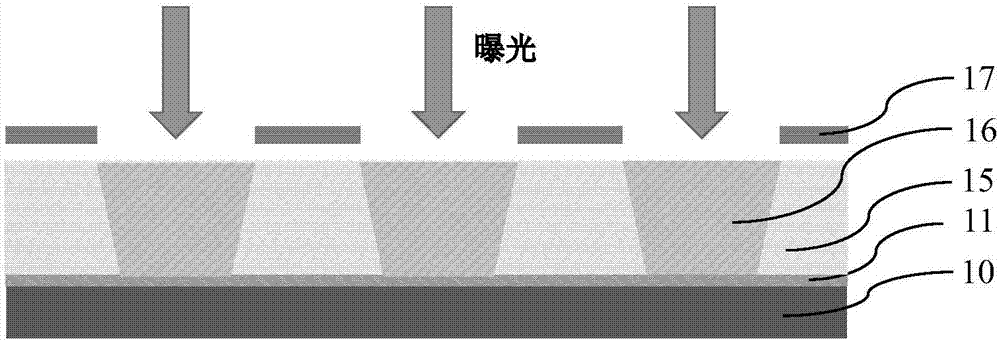
[0035] refer to Figure 6 In this embodiment, a...


PUM

PropertyMeasurementUnit
thicknessaaaaaaaaaa
thicknessaaaaaaaaaa
thicknessaaaaaaaaaa

Abstract

The invention relates to a pixel definition layer and a preparation method and an application thereof. The pixel definition layer comprises a first pixel definition layer and a second pixel definition layer stacked on the first pixel definition layer; the first pixel definition layer is prepared from at least one kind of the materials of unitary or multi-element metal oxide of non-rare-earth elements, unitary or multi-element metal nitride of non-rare-earth elements, unitary or multi-element metal sulfide of non-rare-earth elements, silicon carbide, silicon oxide, silicon nitride or silicon oxynitride; and the second pixel definition layer is prepared from at least one kind of rare earth oxide. By virtue of the pixel definition layer, the problem existing when PI is adopted as a bank layer can be avoided; and the pixel definition layer disclosed in the invention has the bank layer with a clear and definite hydrophilic and hydrophobic boundary line, so that it is ensured thin films with the same height and same uniformity can be obtained by ink of the same volume in different pixels.

Description

technical field [0001] The invention relates to the technical field of organic electroluminescence, in particular to a pixel defining layer and its preparation method and application. Background technique [0002] During the manufacturing process of the printed electroluminescent device, a layer of material used to define pixels must be used. This layer of material is usually called a pixel definition layer (PDL), or called a bank. There are many recessed areas on the Bank layer as "containers" for printing ink, which are called pixel pits, and each pixel pit corresponds to a pixel electrode. The currently widely used process for preparing printed electroluminescent devices is to use an inkjet printing process to fill ink into each pixel pit, and the ink spreads in the area surrounded by the bank; then, at a certain temperature (such as low temperature) Vacuum drying is carried out, and parameters such as solvent volatilization rate and solvent vapor pressure are strictly c...

Claims


Application Information

Patent Timeline
Patent Type & Authority Applications(China)
IPC IPC(8): H01L27/32H01L51/56
CPCH10K59/122H10K71/00
Inventor 李哲
Owner GUANGDONG JUHUA PRINTING DISPLAY TECH CO LTD
Learn More