
A new energy vehicle charging device

A technology of new energy vehicles and charging devices, which is applied in the direction of electric vehicle charging technology, charging stations, coupling devices, etc., can solve the problems of reduced battery life, damaged charging lines, disconnection, etc., to increase the safety of use and stability Sex, the effect of avoiding electric shock accidents

Active Publication Date: 2018-10-16
PUJIANG FEITONG ELECTRONICS TECH CO LTD
View PDF6 Cites 1 Cited by
  • Summary
  • Abstract
  • Description
  • Claims
  • Application Information

AI Technical Summary

Problems solved by technology

[0002] Nowadays, the popularity and utilization rate of new energy vehicles is getting higher and higher. When charging traditional new energy vehicles, the charging gun and the socket of the charging pile body are all frictionally fitted, and the charging wires are usually scattered around the charging device. When someone accidentally kicks and bumps into the charging cable by mistake, the charging gun will be separated from the socket of the charging device and the charging of the new energy vehicle will be suddenly disconnected. This will not only cause damage to the charging cable, but also cause damage to the charging cable. The service life of batteries in new energy vehicles is reduced, and the existing charging piles for new energy vehicles are not safe enough, and electric shock accidents are likely to occur when plugging and unplugging the charging gun

Method used


Image

  • A new energy vehicle charging device
  • A new energy vehicle charging device
  • A new energy vehicle charging device

Examples


Embodiment Construction

[0020] The preferred embodiments of the present invention will be described in detail below in conjunction with the accompanying drawings, so that the advantages and features of the present invention can be more easily understood by those skilled in the art, so as to define the protection scope of the present invention more clearly.

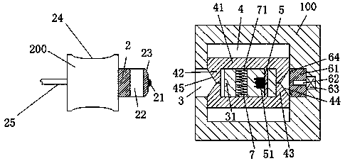
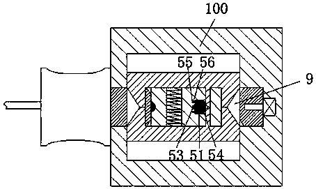
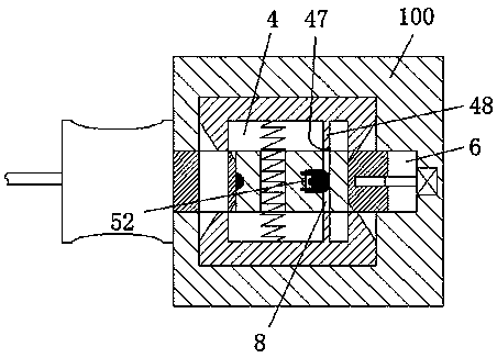
[0021] refer to Figure 1-4 A new energy vehicle charging device shown includes a charging pile body 100 and a charging gun 200 used to cooperate with the charging pile body 100. The left end of the charging gun 200 is connected to the new energy vehicle through a charging line 25. In addition, the charging gun 200 is provided with an arc groove 24, which is convenient for the staff to grasp and prevent the hand from slipping. The middle part of the right end face is provided with a first bumper 21, and the locking bar 2 is provided with a locking groove 22 that penetrates up and down. The middle part is provided with a first conductive port 31,...


PUM


Abstract

The invention discloses a new energy vehicle charging device, which comprises a charging pile body and a charging gun used to cooperate with the charging pile body, the left end surface of the charging gun is connected to the new energy vehicle through a charging line, and the charging There is an arc groove in the gun, a locking bar is set in the middle of the right end face of the charging gun, a first bump is set in the middle of the right end face of the locking bar, and a locking groove penetrating up and down is set in the locking bar. An insertion cavity is provided on the left end surface of the charging pile body, and a first conductive port is provided in the middle of the right end wall of the insertion cavity, and two sliding grooves on the left end that communicate with the insertion cavity are arranged in the front and back of the charging pile body. There are two sliding frames correspondingly arranged in the two sliding grooves. The present invention has the advantages of simple structure, safety and reliability, simple and convenient operation, and convenient plugging and unplugging of the charging gun.

Description

technical field [0001] The invention relates to the technical field of new energy vehicles, in particular to a charging device for new energy vehicles. Background technique [0002] Nowadays, the popularity and utilization rate of new energy vehicles is getting higher and higher. When charging traditional new energy vehicles, the charging gun and the socket of the charging pile body are all frictionally fitted, and the charging wires are usually scattered around the charging device. When someone accidentally kicks and bumps into the charging cable by mistake, the charging gun will be separated from the socket of the charging device and the charging of the new energy vehicle will be suddenly disconnected. This will not only cause damage to the charging cable, but also cause damage to the charging cable. The service life of batteries in new energy vehicles is reduced, and the existing charging piles for new energy vehicles are not safe enough, and electric shock accidents are ...

Claims


Application Information

Patent Timeline
Patent Type & Authority Patents(China)
IPC IPC(8): B60L11/18H01R13/639H01R13/703H01R13/633
CPCB60L53/16H01R13/633H01R13/639H01R13/7036Y02T10/70Y02T10/7072Y02T90/14
Inventor 韦树军
Owner PUJIANG FEITONG ELECTRONICS TECH CO LTD
Learn More