
Planet continuous mill

A grinding machine and planetary technology, applied in the field of grinding, can solve the problems of time-consuming and labor-intensive work, low grinding efficiency, etc., and achieve the effect of good grinding effect, strong automatic cleaning ability and reasonable structure

Inactive Publication Date: 2017-11-28
义乌市台荣超硬制品有限公司
View PDF6 Cites 11 Cited by
  • Summary
  • Abstract
  • Description
  • Claims
  • Application Information

AI Technical Summary

Problems solved by technology

This requires the workpiece to be transposed on multiple grinding machines, which is time-consuming and labor-intensive, the labor intensity of the workers is relatively high, and the grinding efficiency is low

Method used


Image

  • Planet continuous mill
  • Planet continuous mill
  • Planet continuous mill

Examples


Embodiment 1

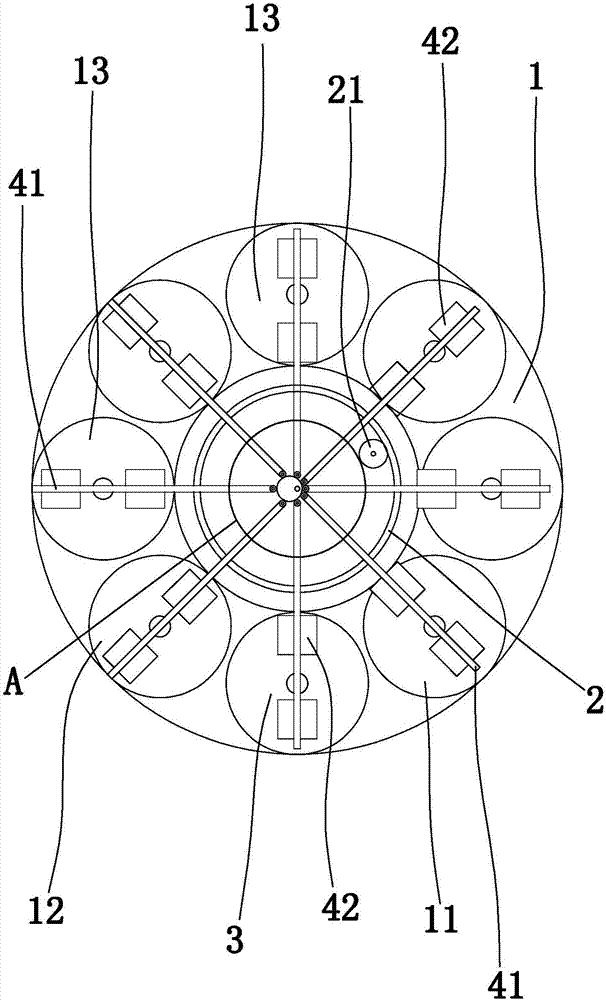
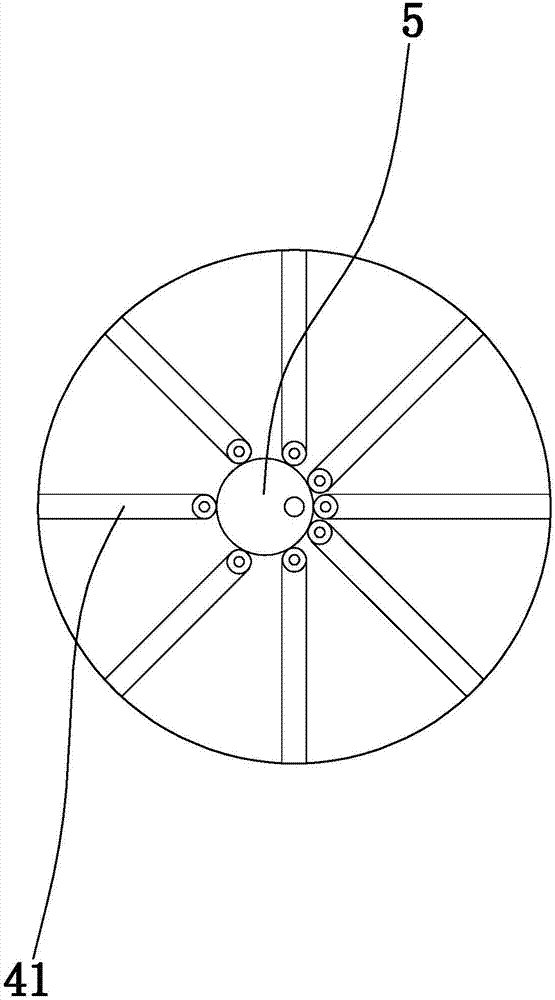
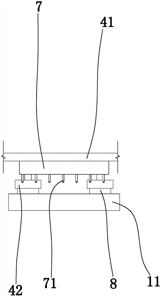
[0024] Embodiment 1: as Figure 1 to Figure 2 In the illustrated embodiment, a planetary continuous mill comprising

[0025] The main frame 1, the vacant station, the drive ring gear 2 and the main motor for driving the drive ring gear to rotate;

[0026] The main frame is provided with a starting mill 11, a terminal mill 12 and a number of intermediate mills 13, the vacant station includes a support table 3, the initial mill includes a starting mill, the terminal mill includes a terminal mill, and the middle mill The machine includes the middle grinding disc, the starting grinding disc, each intermediate grinding disc, the terminal grinding disc and the support table are distributed in sequence along the circumference of the driving ring gear;

[0027] The drive ring gear is rotatably connected to the main frame, the axis of the drive ring gear is vertical, and several workpiece positioning structures are arranged on the drive ring gear, and the workpiece positioning structu...

Embodiment 2

[0037] Embodiment 2: the basic structure and implementation mode of this embodiment are the same as embodiment 1, and its difference is, as Figure 3 to Figure 4As shown in , the main frame is provided with an air supply cylinder block 61, a fixed sliding seat 62 and a gear shaft 63 connected in rotation with the main frame, a driven gear is provided on the gear shaft, and a driving gear is provided on the output shaft of the main motor. Gear, the driving gear meshes with the driven gear, the gear shaft is provided with a starting plate 64 coaxially connected with the gear shaft, the starting plate is provided with an eccentric rod 65, and the air supply cylinder body is provided with a sliding seal for the air supply cylinder body. The air supply piston 611, the air supply piston divides the interior of the air supply cylinder body into an air supply chamber 61a and an adapting chamber 61b that communicates with the outside world, the air supply piston is provided with a pisto...


PUM


Abstract

The invention discloses a planet continuous mill which comprises a main rack, empty stations, a drive gear ring and a main motor. A starting mill, a terminal mill and multiple middle mills are arranged on the main rack. Each empty station comprises a supporting table. A starting mill disc, middle mill discs, a terminal mill disc and the supporting tables are sequentially distributed in the circumferential direction of the drive gear ring. The drive gear ring is rotationally connected with the main rack. Multiple workpiece locating structures are arranged on the drive gear ring. A workpiece locating groove is formed in the bottom of each gravity press block. At least one vertical sliding rod is arranged on each transverse sliding rail rod. The vertical sliding rods are connected with the transverse sliding rail rods through locating pins. A vertical sliding groove is formed in each gravity press block. The vertical siding rods are in sliding fit with the vertical sliding grooves in the corresponding gravity press blocks. The planet continuous mill has the beneficial effects that workpieces can be effectively ground continuously, grinding machining from rough to fine can be achieved through one-time grinding, and the machining process is convenient, fast and efficient; and the automatic clearing capacity of grinding waste is high, the grinding furnaces can be cleared in advance before the workpieces arrive, and the grinding effect is good.

Description

technical field [0001] The invention belongs to the technical field of grinding processing, in particular to a planetary continuous grinding machine. Background technique [0002] Grinding devices such as flat grinders have been widely used at present. The grinding device can grind one or more surfaces of the workpiece (such as a plate) so that the surface precision (surface roughness) of the workpiece can reach the required level. In the actual grinding process, the workpiece often needs to go through multiple processing processes (such as a rough grinding, a second rough grinding, a fine grinding, a second fine grinding, etc.) in order to meet the requirements. This requires the workpiece to be transposed on multiple grinding machines, which is time-consuming and labor-intensive, the labor intensity of the workers is relatively high, and the grinding efficiency is low. Contents of the invention [0003] In order to overcome the deficiencies in the prior art, the presen...

Claims


Application Information

Patent Timeline
Patent Type & Authority Applications(China)
IPC IPC(8): B24B27/00B24B41/06B24B55/06
CPCB24B27/0023B24B41/06B24B55/06
Inventor 陈政伟
Owner 义乌市台荣超硬制品有限公司
Learn More