
Vehicle battery charging cooling system and method

A battery charging and vehicle technology, applied in the field of vehicles, can solve the problems of low cooling efficiency, affecting fast charging efficiency, uneven cooling effect of batteries, etc.

Active Publication Date: 2017-11-24
GAC AION NEW ENERGY AUTOMOBILE CO LTD
View PDF10 Cites 25 Cited by
  • Summary
  • Abstract
  • Description
  • Claims
  • Application Information

AI Technical Summary

Problems solved by technology

However, at different battery temperatures, the charging capacity and charging efficiency of the power battery vary greatly. The temperature of the fast charging battery rises rapidly in a high temperature environment. If the temperature rise of the battery cannot be effectively controlled, the battery’s allowable charging capacity will drop rapidly; if The battery temperature cannot be effectively lowered. On the one hand, it is easy to cause the danger of charging the power battery. On the other hand, the charging efficiency of the battery decreases, and the time of fast charging is greatly prolonged, which affects the efficiency of fast charging.
[0003] To solve this problem, the traditional method is to blow the cold air from the air conditioner compressor into the battery pack for circulation to cool the battery. However, when the battery pack contains multiple batteries, this method has low cooling efficiency and poor battery cooling effect. The problem of uniformity and large temperature difference of multiple batteries

Method used


Image

  • Vehicle battery charging cooling system and method
  • Vehicle battery charging cooling system and method
  • Vehicle battery charging cooling system and method

Examples


Embodiment Construction

[0027] In order to make the object, technical solution and advantages of the present invention clearer, the present invention will be further described in detail below in conjunction with the accompanying drawings and embodiments. It should be understood that the specific embodiments described here are only used to explain the present invention, not to limit the present invention.

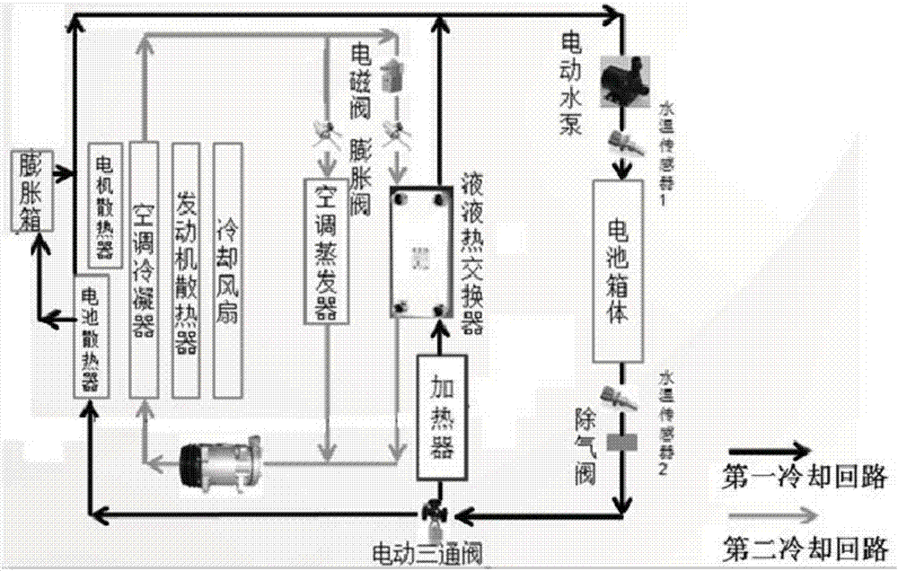
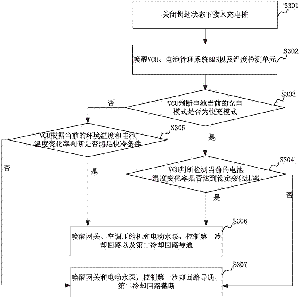
[0028] figure 1 A schematic diagram of a logic framework of a system for charging and cooling a vehicle battery of an embodiment; figure 1 As shown, the vehicle battery charging and cooling system in this embodiment includes: a temperature detection unit, a control unit, a first cooling circuit, and a second cooling circuit; initially, the first cooling circuit and the second cooling circuit are both cut off .

[0029] The temperature detection unit is used to obtain the ambient temperature and the battery temperature during the charging process of the battery, and obtain the temperature change r...


PUM


Abstract

The present invention relates to a vehicle battery charging cooling system and method. The system includes a temperature detection unit which is configured to obtain ambient temperature and battery temperature during a battery charging process and obtain a battery temperature change rate according to the battery temperature; and a control unit for controlling on / off of a first cooling circuit and a second cooling circuit according to current ambient temperature and the battery temperature change rate; when in on state, the first cooling circuit can cool a battery on the basis of flow of a cooling liquid; when in on state, the second cooling circuit is configured to cool the cooling liquid in the first cooling circuit by an air-conditioning refrigerant of a vehicle, wherein the cooling condition is that the ambient temperature is greater than or equal to a set first temperature threshold, and the battery temperature change rate is greater than or equal to a set change rate. The vehicle battery charging cooling system can achieve different heat dissipation requirements during the vehicle battery charging process.

Description

technical field [0001] The invention relates to the field of vehicle technology, in particular to a system and method for charging and cooling a vehicle battery. Background technique [0002] The core problems faced by electric vehicles are insufficient mileage and insufficient configuration of charging settings. Fast charging piles can solve the problem of charging and cooling the batteries of electric vehicles. However, at different battery temperatures, the charging capacity and charging efficiency of the power battery vary greatly. The temperature of the fast charging battery rises rapidly in a high temperature environment. If the temperature rise of the battery cannot be effectively controlled, the battery’s allowable charging capacity will drop rapidly; if If the battery temperature cannot be effectively lowered, on the one hand, it is easy to cause the danger of charging the power battery. On the other hand, the charging efficiency of the battery decreases, and the ti...

Claims


Application Information

Patent Timeline
IPC IPC(8): H01M10/613H01M10/615H01M10/617H01M10/625H01M10/633H01M10/635H01M10/6567H01M10/6568H01M10/663H01M10/48B60L11/18
CPCB60L58/26H01M10/482H01M10/486H01M10/613H01M10/615H01M10/617H01M10/625H01M10/633H01M10/635H01M10/6567H01M10/6568H01M10/663H01M2220/20Y02E60/10Y02T10/70
Inventor 符兴锋唐湘波李昌明曾建宏王军姚伟浩
Owner GAC AION NEW ENERGY AUTOMOBILE CO LTD
Learn More