Wire storage mechanism

A wire storage and wire storage technology, which is applied to the field of wire harness down-line spigot processing equipment, can solve the problems of low spigot efficiency and large workload, and achieve the effect of improving spigot efficiency.

Pending Publication Date: 2017-11-24
HEBI HAICHANG SPECIAL EQUIP
View PDF12 Cites 2 Cited by
  • Summary
  • Abstract
  • Description
  • Claims
  • Application Information

AI Technical Summary

Problems solved by technology

[0003] The present invention aims to solve technical problems such as low plug-in efficiency and heavy workload due to manual hand-held plug-in production during the production of the existing wire harness plug-in, thereby providing a wire storage. Temporary storage and adjustment of the insertion sequence of different diameter wires

Method used


Image

  • Wire storage mechanism
  • Wire storage mechanism
  • Wire storage mechanism

Examples


Embodiment Construction

[0015] The following will clearly and completely describe the technical solutions in the embodiments of the present invention with reference to the accompanying drawings in the embodiments of the present invention. Obviously, the described embodiments are only some, not all, embodiments of the present invention. Based on the embodiments of the present invention, all other embodiments obtained by persons of ordinary skill in the art without making creative efforts belong to the protection scope of the present invention.

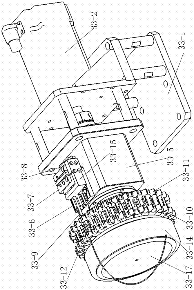
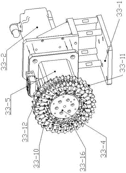
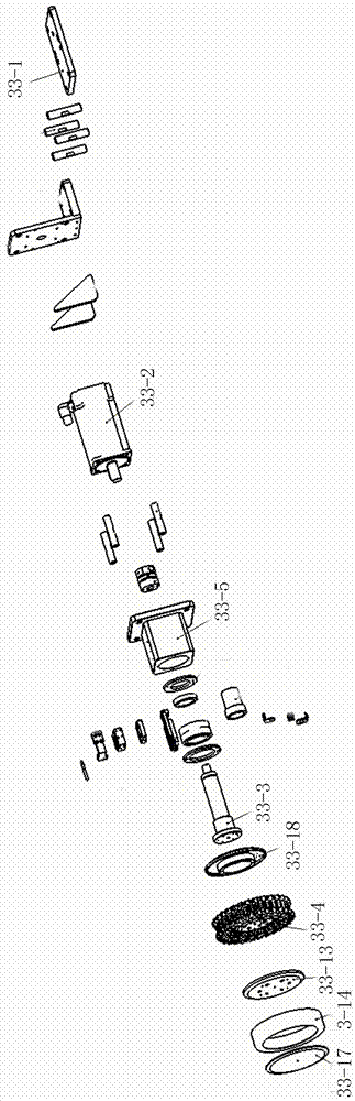
[0016] Such as Figure 1-4 As shown, a wire storage mechanism includes a wire storage installation plate 33-1, a wire storage motor 33-2 is installed on the wire storage installation plate 33-1, and the output shaft of the wire storage motor 33-2 passes through the wire storage rotating shaft 33 -3 is connected with the line storage assembly; the line storage toggle assembly is arranged on the line storage rotating shaft 33-3, and the push rod 33-9 of the line...


PUM


Abstract

The invention discloses a wire storage mechanism. The wire storage mechanism comprises a wire storage mounting plate, and a wire storage motor is arranged on the wire storage mounting plate; an output shaft of the wire storage motor is connected with a wire storage assembly through a wire storage rotating shaft; a wire storage poking assembly is arranged on the wire storage rotating shaft, and a push rod of the wire storage poking assembly is matched with a clamping unit of the wire storage assembly. According to the mechanism, a wire storage rotary disc is driven by the wire storage motor to rotate, and the wire storage assembly on the wire storage rotary disc rotates along with the wire storage rotary disc so that corresponding storage space can be provided for wires with different diameters. The push rod of the wire storage poking assembly pokes a pressing block unit of the wire storage assembly under the action of a first pneumatic sliding table and a second pneumatic sliding table, and the wire storage assembly clamps and releases wire rods. The first pneumatic sliding table achieves insertion and retraction of the push rod between a transverse baffle and the pressing block unit; the second pneumatic sliding table makes the push rod poke the pressing block unit. By means of the mechanism, the wire rods can be automatically stored, the mechanism does not need to be held manually, and the plugging efficiency is improved.

Description

technical field [0001] The invention belongs to the technical field of wire harness off-line insertion end processing equipment, and in particular relates to a wire storage mechanism for inserting terminals into plastic sheaths in the wire harness industry. Background technique [0002] At present, domestic wiring harness enterprises are first to make the wire harness required for the plug-in sheath off-line, and then transfer it from the logistics to the streamline area to complete the plug-in terminal manually, resulting in a large number of products in progress, high labor intensity for the plug-in workers, and unstable quality. Contents of the invention [0003] The present invention aims to solve technical problems such as low plug-in efficiency and heavy workload due to manual hand-held plug-in production during the production of the existing wire harness plug-in, thereby providing a wire storage. The function of temporarily storing and adjusting the insertion sequen...

Claims


Application Information

Patent Timeline
IPC IPC(8): B65D25/10B65D25/00B65D85/00H01R43/20
CPCH01R43/20B65D25/00B65D25/10B65D85/00
Inventor 崔炳艺张玉平张海洋程朝锋李德阳李振涛
Owner HEBI HAICHANG SPECIAL EQUIP
Why Eureka
Try Eureka