
Reference signal transmission method and device

A reference signal and reference signal sequence technology, applied in the field of reference signal transmission, can solve the problems of shortened transmission distance, loss of array gain, poor cell-specific signal quality, etc., to control mutual interference, control overhead, and solve array gain. and coverage effects

Active Publication Date: 2021-04-20
HUAWEI TECH CO LTD
View PDF7 Cites 0 Cited by
  • Summary
  • Abstract
  • Description
  • Claims
  • Application Information

AI Technical Summary

Problems solved by technology

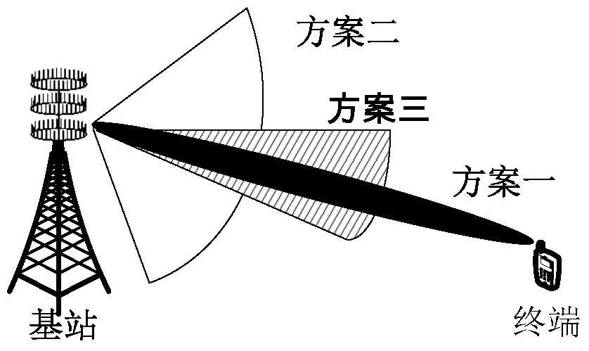
In contrast, for cell-specific (English full name: Cell-specific) signals that need to be sent to all terminals or most terminals in the cell, such as multicast messages, broadcast messages, control signals, etc., in order to enable all terminals within the coverage area to receive To these Cell-specific signals (without loss of generality, this application is collectively referred to as common control information, correspondingly, the channel carrying the common control information is the common control channel) and reference signals for detecting these common control information, it is It is necessary for the base station to use M-MIMO technology to generate a wide beam similar to omnidirectional transmission (English full name: omni-directional transmission), or to generate a wide beam with a width of 120 degrees under a three-sector configuration (see figure 2 Solution 2 in ), but unfortunately, the use of wide beams will lose array gain and shorten the transmission distance, so terminals at the edge of the cell often cannot receive Cell-specific signals or the quality of received Cell-specific signals very poor
This is a contradiction, so it is often necessary to make a compromise between array gain (or beam width) and coverage, namely figure 2 Option 3 in , however, Option 3 still does not fundamentally solve the contradiction between array gain and coverage

Method used


Image

  • Reference signal transmission method and device
  • Reference signal transmission method and device
  • Reference signal transmission method and device

Examples


Embodiment 1

[0108] A base station with M antenna ports generates cell control reference information for detecting common control information before sending common control information. In this embodiment, the cell control reference information for detecting common control information is a CCRS sequence.

[0109] The base station maps the common control information and the cell control reference information to one or more resource units RU of N antenna ports, and then uses the one or more RUs to detect the common control information and the common The cell control reference information of the control information is sent to terminals within the coverage of the base station. The foregoing N antenna ports are a part of the M antenna ports of the base station.

[0110] Before sending the common control information, the base station needs to generate a CCRS sequence for detecting the common control information. In order to be consistent with the CCRS sequences generated by the terminal, the base ...

Embodiment 2

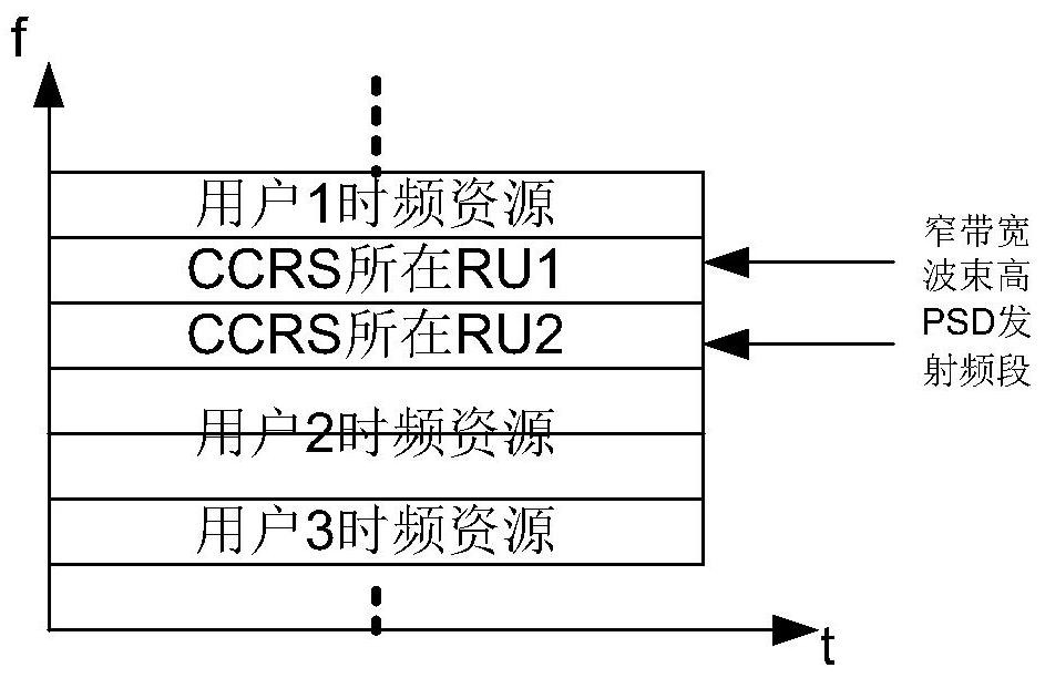
[0188] The CCRS sequence solution shown in the first embodiment discusses that there is only one common control channel, that is, there is only one CCRS sequence frequency band in the entire frequency band. When the transmission bandwidth of the base station is relatively large, such as 200MHz bandwidth, the entire bandwidth can be divided into multiple 20MHz or even narrower bandwidth subbands by the base station, or the system itself is aggregated by multiple 20MHz bandwidth carriers (without loss of generality). characteristics, which are collectively represented by multiple subbands below), the base station can be designed to send common control channels in multiple subbands, such as Figure 7 As shown, the common control channel is distributed on the time-frequency resources of different subbands of a frame, where each space represents an RU, and the oblique part is the resource occupied by the common control channel. It can be seen that each subband can independently sche...

Embodiment 3

[0191] Figure 8According to the above embodiments, a structural block diagram of an apparatus for sending and receiving cell control reference information is provided. For ease of description, only the parts related to the embodiment of the present application are shown. And in this embodiment, the device can be either a base station or a terminal.

[0192] In this device, the base station 100 includes: an antenna 110 , a transmitter 120 , a processor 130 , and a memory 140 . The antenna 110 has M antenna ports, and N antenna ports are dedicated to sending common control information and CCRS sequences used to detect the common control information.

[0193] The transmitter 120 is configured to transmit common control information and CCRS sequences to terminals within the coverage of the base station through N antenna ports through one or more RUs.

[0194] The memory 140 is used for storing mapping patterns, program codes and pseudo-random sequences executable by the proces...


PUM


Abstract

The embodiment of the present application provides a method and equipment for sending reference signals. The embodiment of the present application relates to the field of communication technology and is used to solve the contradiction between coverage and array gain. The method includes: a base station with M antenna ports needs to send a common generating cell control reference information for detecting the common control information before the control information; the base station maps the common control information and the cell control reference information to one or more resource units RU of N antenna ports, The N antenna ports are part of the M antenna ports; the base station sends the common control information and cell control reference information for detecting the common control information to the Terminals within the coverage of the base station. The method of concentrating the power of the entire frequency band on one or more RUs of N antenna ports can effectively enhance coverage without affecting data transmission on other RUs.

Description

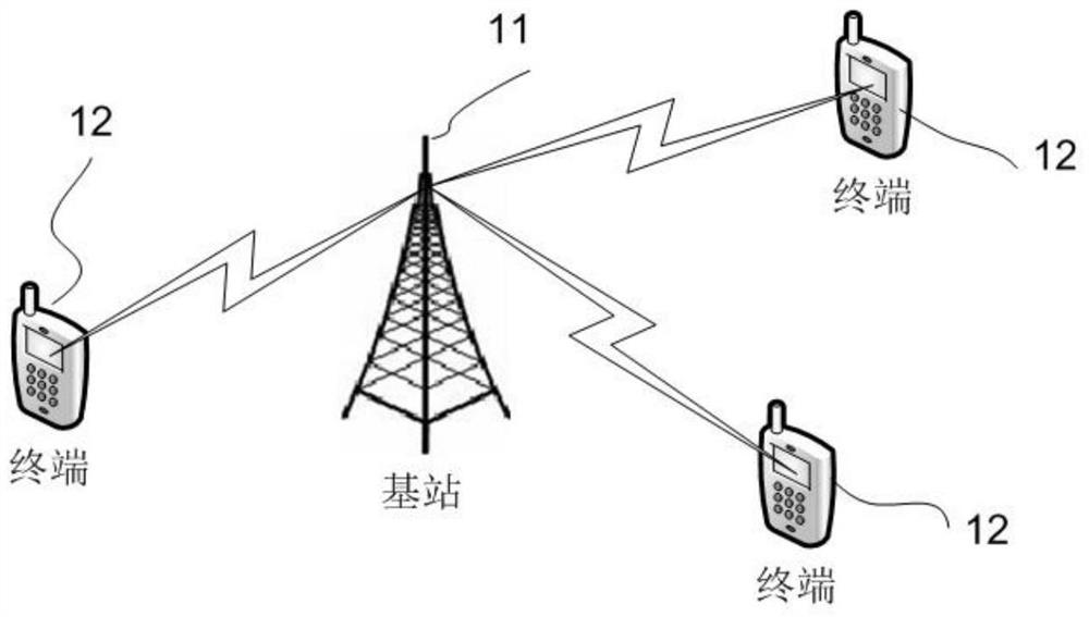
technical field [0001] The embodiments of the present application relate to the technical field of communication, and more specifically, to a method for sending a reference signal used for detecting common control information or multicast / broadcast information in wireless communication. Background technique [0002] The current wireless communication technology has been developed to LTE (full name in Chinese: Long Term Evolution; full name in English: LongTerm Evolution) system, with figure 1 For example, the existing LTE system includes multiple cells, and each cell has a base station 11 and multiple terminals 12, and the base station sends public control information and data to the terminals, as well as references for detecting public control information and data. Signal. [0003] In the existing LTE R8-R12 system, there are three main types of reference signals used for downlink channel measurement and data demodulation: CRS (full name in Chinese: Cell-specific Reference...

Claims


Application Information

Patent Timeline
Patent Type & Authority Patents(China)
IPC IPC(8): H04L5/00H04W72/04
CPCH04L5/0048H04L5/0053H04W72/0453H04W72/20H04B7/0452H04B7/0617H04J11/005H04L5/005H04L27/261H04B7/0413H04J11/0069H04L5/0007H04J13/0062
Inventor 刘瑾毕晓艳葛士斌
Owner HUAWEI TECH CO LTD
Learn More