
Broadband high-efficiency and high-gain circular-polarized array antenna

An array antenna and circularly polarized technology, applied in the field of broadband high-efficiency and high-gain circularly polarized array antennas, can solve the problem of increased loss, difficulty in patch array antennas, high-gain array antennas, and reflect array antennas in improving aperture efficiency feeds Antenna installation accuracy and other issues, to achieve the effect of easy design and strong scalability

Active Publication Date: 2017-11-21
UNIV OF ELECTRONIC SCI & TECH OF CHINA
View PDF4 Cites 7 Cited by
  • Summary
  • Abstract
  • Description
  • Claims
  • Application Information

AI Technical Summary

Problems solved by technology

At present, the antennas designed and applied in the terahertz frequency band are mainly patch array antennas and planar reflectarray antennas. Due to the increased loss of the dielectric substrate in the terahertz frequency band, patch array antennas are difficult to design high-gain array antennas; at the same time, reflectarray The antenna has problems such as difficulty in improving the aperture efficiency and the installation accuracy of the feed antenna position

Method used


Image

  • Broadband high-efficiency and high-gain circular-polarized array antenna
  • Broadband high-efficiency and high-gain circular-polarized array antenna
  • Broadband high-efficiency and high-gain circular-polarized array antenna

Examples


Embodiment Construction

[0014] The present invention will be described in further detail below in conjunction with the accompanying drawings and embodiments.

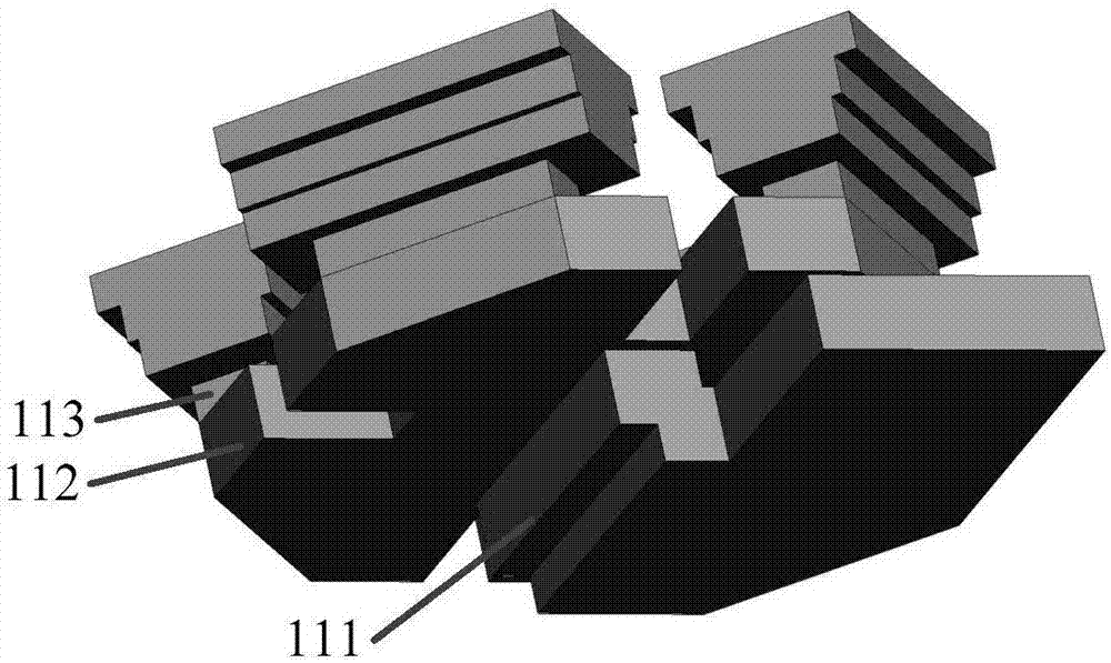
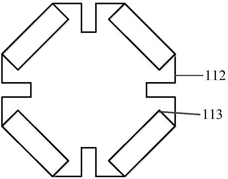
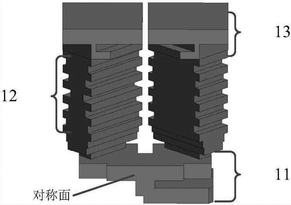
[0015] This embodiment provides an 8×8 broadband high-efficiency and high-gain circularly polarized array antenna, the structure of which is as follows Image 6 As shown, it includes a broadband circularly polarized subarray antenna unit and a broadband feed network, wherein the broadband circularly polarized subarray antenna mainly includes a subarray feed network (11), a broadband complementary phase shifter (12) and a broadband radiation unit (13); The sub-array feed network (11) includes a feed structure (111), a power division coupling cavity structure (112) and a coupling slit (113) located on the upper surface of the power division coupling cavity structure, as figure 1 As shown, the feed structure (111) is connected to the lower surface of the power division coupling cavity structure; the power division coupling cavity structure is a s...


PUM


Abstract

The invention belongs to the field of the millimeter wave antenna, and provides a broadband high-efficiency and high-gain circular-polarized array antenna which is suitable for a wireless communication system in Terahertz band. The broadband high-efficiency and high-gain circular-polarized array antenna comprises a broadband circular-polarized sub-array antenna unit and a broadband feed network; the broadband circular-polarized sub-array antenna unit comprises a sub-array feed network, a complementary phase shifter and a radiation unit; the sub-array feed network comprises a feed structure, a power-division coupling cavity structure and a coupling gap arranged on the upper surface of the power-division coupling cavity structure; the power-division coupling cavity structure is a square cavity having four corners with chamfers, and a perturbation structure is arranged at the centre of each of four sides; a coupling gap is correspondingly formed at each chamber position as the dual-polarized output port; the output port is connected with the complementary phase shifter, and the output end of the complementary phase shifter is connected with a radiation unit. The antenna provided by the invention adopts the broadband power-divider structure and the broadband phase shifter structure, so that the wide axial ratio bandwidth (more than 28.5%) and standing wave bandwidth (more than 28.5%) are provided.

Description

technical field [0001] The invention belongs to the field of millimeter-wave antennas, in particular to a wide-band, high-efficiency, high-gain circularly polarized array antenna. Background technique [0002] As the communication capacity gradually increases, the operating bandwidth and signal-to-noise ratio requirements of the communication system also increase; the antenna, as a key component of the wireless communication system, plays a decisive role in the overall performance of the communication system, such as: the polarization purity of the antenna and Gain directly affects the system signal-to-noise ratio. At present, the antennas designed and applied in the terahertz frequency band are mainly patch array antennas and planar reflectarray antennas. Due to the increased loss of the dielectric substrate in the terahertz frequency band, patch array antennas are difficult to design high-gain array antennas; at the same time, reflectarray The antenna has problems such ...

Claims


Application Information

Patent Timeline
IPC IPC(8): H01Q1/50H01Q21/24H01Q23/00
CPCH01Q1/50H01Q21/24H01Q23/00
Inventor 程钰间周明明阿泽刘双樊勇宋开军张波林先其张永鸿
Owner UNIV OF ELECTRONIC SCI & TECH OF CHINA
Learn More