
Pivot pin type pull pressure sensor

A pull pressure sensor and pull pressure technology, applied in the field of sensors, can solve problems such as unsatisfactory waterproof performance, unusable sensors, and affecting work efficiency, and achieve good waterproof performance, reasonable structure, and continuity.

Active Publication Date: 2017-11-17
BENGBU SUNMOON INSTR INST
View PDF3 Cites 0 Cited by
  • Summary
  • Abstract
  • Description
  • Claims
  • Application Information

AI Technical Summary

Problems solved by technology

The existing pin-type tension-pressure sensor has only one tension-pressure test unit, so the problem is that when the pin-type tension-pressure sensor is used on field equipment, once the test unit breaks down, the entire sensor cannot be used. To replace the sensor, the equipment must be stopped, which will affect the work efficiency
In addition, the existing pin-type tensile and pressure sensors usually have unsatisfactory waterproof performance. When they are used on field equipment, they are prone to water ingress in rainy weather, resulting in a high failure rate.

Method used


Image

  • Pivot pin type pull pressure sensor
  • Pivot pin type pull pressure sensor
  • Pivot pin type pull pressure sensor

Examples


Embodiment Construction

[0010] The present invention is further described below in conjunction with embodiment and accompanying drawing.

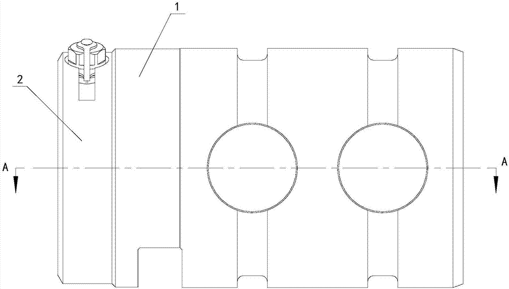
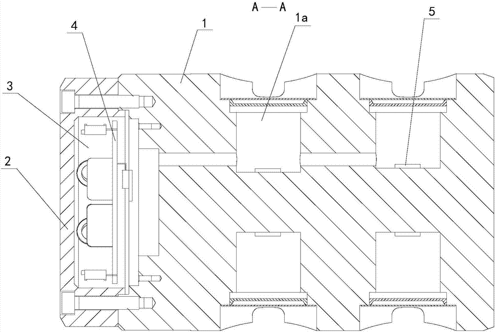
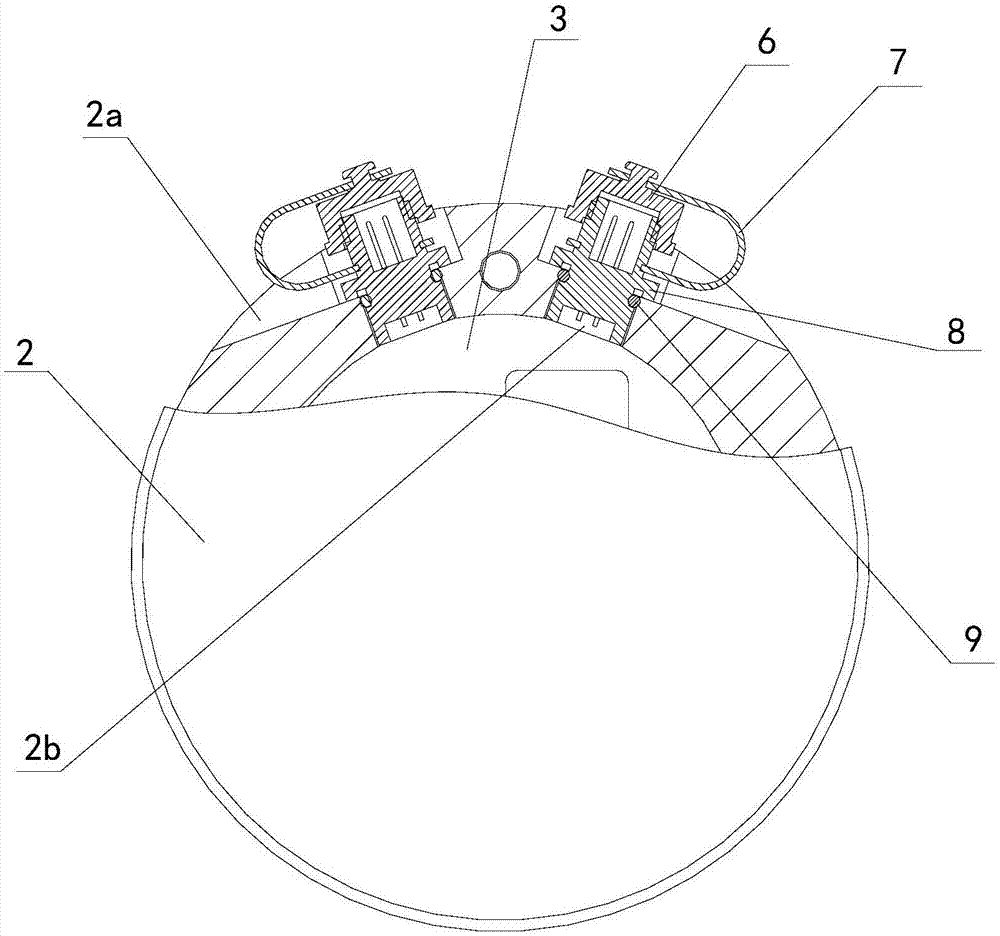
[0011] see figure 1 , figure 2 , image 3

[0012] The pin-type tensile pressure sensor provided by the present invention has a cylindrical strain body 1, four blind holes 1a are arranged on the strain body 1, and strain gauges 5 are attached to the inner walls of the blind holes 1a. One end of the strain body 1 is connected with an end cover 2 , and an electrical compartment 3 is formed between the end cover 2 and the strain body 1 . The electrical compartment 3 is equipped with a transmission circuit board 4 , and an output terminal 8 is installed on the outside of the end cover 3 .

[0013] In the present invention, there are two sets of strain gauges 5, two output terminals 8, and two pull-pressure test units, each pull-pressure test unit consists of a set of strain gauges 5, an output terminal 8 and a transmission circuit board 4 The above transmission c...


PUM


Abstract

The invention relates to a pivot pin type pull pressure sensor. Strain gauges are attached on an inner wall of a blind hole on a strain body, the strain body and a connected end cap form an electrical bin, the electrical bin is internally equipped with a transmission circuit board, the end cap is equipped with output terminals, the strain gauges, the transmission circuit board and the output terminals form pull pressure test units, the strain gauges have two sets, the output terminals are two, each pull pressure test unit comprises a set of strain gauges, one output terminal and a transmission circuit on the transmission circuit board, a surface of the end cap is provided with a pair of notches, a bottom surface of the notches is inclined relative to the horizontal plane, the bottom surface of the notches is provided with through holes communicated with the electrical bin, and the output terminals are mounted on the through holes. During use, one test unit can be started, the other one is the standby one, when the started test unit is in fault, the standby one can be started, work continuity of the sensor can be guaranteed, the sensor is mounted on outdoor work equipment, in rainy days, no water is in the notches.

Description

technical field [0001] The invention relates to a sensor, in particular to a pivot pin type tension pressure sensor. Background technique [0002] The shaft pin tension pressure sensor is a sensor for measuring tension and pressure. The existing pin-type tension-pressure sensor has only one tension-pressure test unit, so the problem is that when the pin-type tension-pressure sensor is used on field equipment, once the test unit breaks down, the entire sensor cannot be used. To replace the sensor, the equipment must be stopped, which will affect the work efficiency. In addition, the existing pin-type tensile and pressure sensors usually have unsatisfactory waterproof performance. When they are used on field equipment, they are prone to water ingress in rainy weather, resulting in a high failure rate. Contents of the invention [0003] The purpose of the present invention is to provide a pivot pin type tension pressure sensor, which has two test units, the two test units c...

Claims


Application Information

Patent Timeline
Patent Type & Authority Applications(China)
IPC IPC(8): G01L1/00
CPCG01L1/00
Inventor 陈虹陈海燕陈荡李剑吴红军马训陈明业
Owner BENGBU SUNMOON INSTR INST
Learn More