
Circuit measurement calibration method and calibration device of three-dimensional photoelectric vibration measuring instrument

A technology of vibration measurement and calibration method, which is applied in the direction of measuring devices, measuring ultrasonic/sonic/infrasonic waves, instruments, etc., to achieve the effect of efficient measurement

Pending Publication Date: 2017-11-17
ZHEJIANG MEASUREMENT SCI RES INST
View PDF2 Cites 3 Cited by
  • Summary
  • Abstract
  • Description
  • Claims
  • Application Information

AI Technical Summary

Problems solved by technology

The main technical difficulty involved in this delay is how to demodulate the modulated signal output by the laser optical head through the circuit in real time and quickly, and then display the mode shape in real time, etc.

Method used


Image

  • Circuit measurement calibration method and calibration device of three-dimensional photoelectric vibration measuring instrument
  • Circuit measurement calibration method and calibration device of three-dimensional photoelectric vibration measuring instrument
  • Circuit measurement calibration method and calibration device of three-dimensional photoelectric vibration measuring instrument

Examples


Embodiment 1

[0028] The phase shift characteristic is a comparative quantity. In order to realize the measurement of the phase shift between the response signal of the laser vibrometer and the initial sinusoidal modulation signal, it is necessary to realize the synchronous acquisition of two channels of the same frequency signal, and to exclude other factors such as inconsistency in signal amplitude. Impact. The spectrum analysis method is used to measure the phase shift characteristics, and the whole cycle sampling is used to reduce the error caused by the spectrum leakage.

[0029] The spectrum analysis method uses discrete Fourier transform (DFT) to analyze the spectrum of the two signals under test to obtain their phase-frequency characteristics. The phase difference between the two signals at the fundamental frequency is the phase shift value. Any absolutely integrable periodic signal x(t) can be expanded into a Fourier series in the finite interval [t,t+T]

[0030]

[0031] In fo...

Embodiment 2

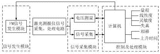
[0047] In this embodiment, the electrical signal calibration method is used to calibrate the rise time of the laser vibrometer, that is, the FM signal excitation whose modulation law is a square wave is input at the input end of its signal acquisition and processing circuit, and the response to the key circuit of the laser vibrometer is The square wave signal is collected and analyzed to obtain its rise time characteristics.

[0048] The square wave signal output by the laser vibrometer is not an ideal square wave signal, but has certain overshoot and zero point oscillation. To achieve accurate measurement of rise time, the steady-state position of the square wave signal waveform must first be accurately located. In order to eliminate the influence of waveform rising overshoot and oscillation, this embodiment uses the mode method to accurately obtain the top value x of the square wave curve T and base value x B .


PUM


Abstract

The present invention relates to a measurement calibration method of a three-dimensional photoelectric vibration measuring instrument system and a key circuit calibration device of the three-dimensional photoelectric vibration measuring instrument system. A measurement calibration mode that a traditional standard vibration table excitation method is adopted to perform measurement calibration on a three-dimensional photoelectric vibration measuring instrument is limited by a vibration table, and the measurement frequency and amplitude of the traditional standard vibration table excitation method are limited. According to the measurement calibration method of the present invention, electrical signal excitation is used to replace actual physical quantity excitation to perform measurement calibration on the photoelectric vibration measuring instrument, that is, FM signals are directly connected into the input ends of the corresponding signal acquisition and processing circuits of the three-dimensional photoelectric vibration measuring instrument to replace physical quantity excitation on the basis of a heterodyne laser interference principle, and therefore, the calibration of the measuring range, linearity, sensitivity, phase shift, delay, rise time, distortion and other parameters of the three-dimensional photoelectric vibration measuring instrument can be realized. With the measurement calibration method and calibration device of the invention adopted, the measurement of the three-dimensional photoelectric vibration measuring instrument system is more accurate, more efficient and more convenient.

Description

technical field [0001] The invention relates to a measurement detection method and a standard device, in particular to a measurement calibration method and a calibration device for a circuit of a three-dimensional photoelectric vibration measuring instrument. Background technique [0002] In the field of precision scientific measuring instruments and meters, there was a certain gap in accuracy and stability between our country and foreign advanced levels in the past. With the continuous advancement of the scientific and technological level of my country's scientific instrumentation industry and the continuous development of industrialization, the accuracy and stability of its products have been greatly improved in some fields. However, due to the influence of the previous market share and influence of foreign products, domestic instruments are facing a lot of pressure: although sometimes the accuracy is not inferior to foreign instruments, but they cannot be recognized by do...

Claims


Application Information

Patent Timeline
Patent Type & Authority Applications(China)
IPC IPC(8): G01H9/00
CPCG01H9/00
Inventor 姚磊韩慧高申平俞醒言陈俭
Owner ZHEJIANG MEASUREMENT SCI RES INST
Learn More