Efficient-recycling chemical-fiber textile wastewater treatment system

A technology of textile wastewater and treatment system, which is applied in textile industrial wastewater treatment, water/sewage treatment, water/sludge/sewage treatment, etc., and can solve the problems of short fiber collection and inability to separate sludge-like pollutants, etc.

Inactive Publication Date: 2017-11-17
HUZHOU CHENGXIN TEXTILE PRINTING & DYEING
View PDF1 Cites 2 Cited by
  • Summary
  • Abstract
  • Description
  • Claims
  • Application Information

AI Technical Summary

Problems solved by technology

[0004] In the Chinese patent with the patent number CN104147836B, a diagonal belt type automatic cleaning fine grid machine is disclosed to remove short fiber pollutants in textile wastewater, but it does not collect short fibers, and it cannot separate textile waste water. Sludge-like pollutants formed by the accumulation of slurry

Method used


Image

  • Efficient-recycling chemical-fiber textile wastewater treatment system
  • Efficient-recycling chemical-fiber textile wastewater treatment system
  • Efficient-recycling chemical-fiber textile wastewater treatment system

Examples


Embodiment

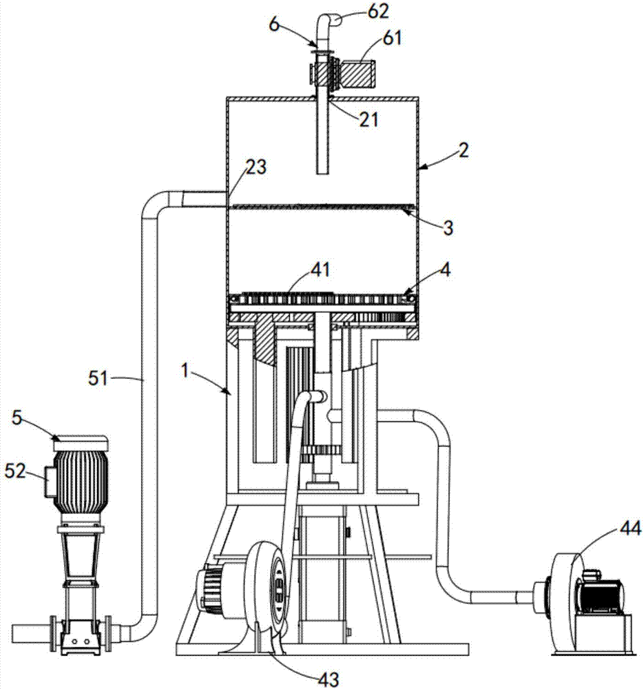
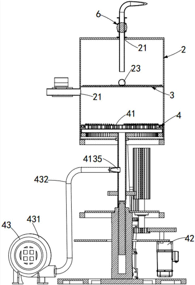
[0065] like figure 1 and figure 2 As shown, an efficient recycling chemical fiber textile wastewater treatment system includes a frame 1, and also includes:

[0066] Compression barrel 2, the compression barrel 2 is fixedly arranged on the upper part of the frame 1, it is cylindrical, and the top is provided with a water outlet 21, the middle of the side wall of the compression barrel 2 is provided with a water inlet 22 and The sludge outlet 23, the water inlet 22 is located below the sludge outlet 23;

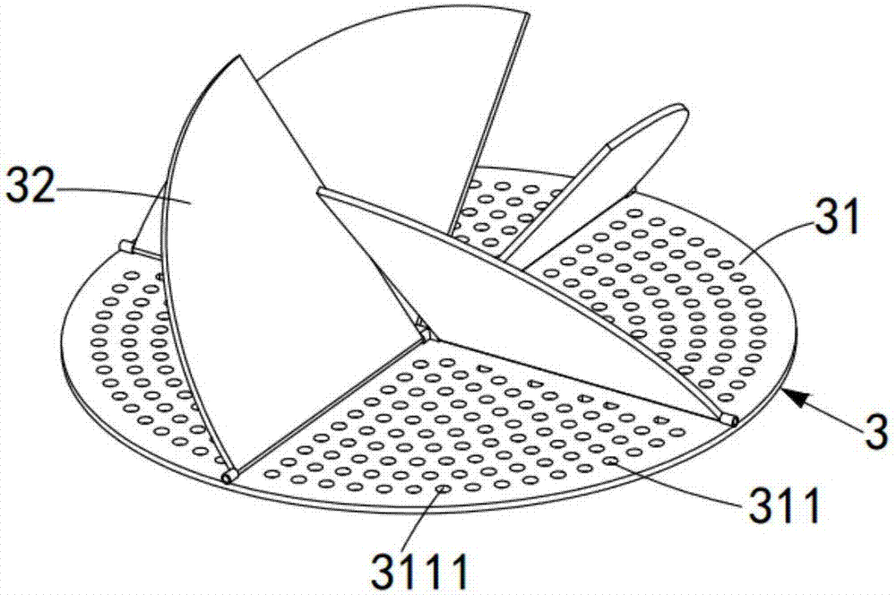
[0067] Filtering mechanism 3, which is fixedly arranged in the middle of the compression barrel 2, which is located between the sludge outlet 23 and the water inlet 22;

[0068] Compression mechanism 4, the compression mechanism 4 is arranged below the filter mechanism 3, which includes a piston push assembly 41, a rotation assembly 42, a blower assembly 43 and a suction assembly 44, and the upper end of the piston push assembly 41 passes through the The compression barrel...

Embodiment approach

[0087] As a preferred embodiment, the rotating assembly 42 includes:

[0088] like Figure 9 and Figure 10 As shown, the rotating unit 421 is arranged below the compression barrel 2 and is fixedly connected with the frame 1;

[0089] A synchronous rotation unit 422, the synchronous rotation unit 422 is located in the compression barrel 2, and is arranged below the piston 412.

[0090] like Figure 9 shown, wherein, the rotating unit 421 includes:

[0091] A rotating motor 4211, the rotating motor 4211 is arranged on one side of the pushing cylinder 411, which is fixedly connected with the frame 1, and a driving gear 4212 is sleeved on the motor shaft;

[0092] A rotating shaft 4213, the rotating shaft 4213 is arranged on one side of the rotating motor 4211, it is rotatably arranged on the frame 1, and a driven gear 4214 is arranged at its end, and the driven gear 4214 is connected with the driving gear 4214. The gears 4212 are engaged, and the upper end of the rotating s...


PUM


Abstract

The invention discloses an efficient recycling chemical fiber textile wastewater treatment system, aiming at solving the separation of short fibers and sludge in textile wastewater, and realizing the recovery and reuse of short fibers, which includes a compression barrel, a filter mechanism and a compressor The mechanism, which inputs the textile sewage into the compression barrel, uses the push piston mechanism to squeeze the sewage from bottom to top, combined with the interception function of the filter mechanism, makes the waste water, sludge and short fibers in the compression barrel from top to bottom. Automatic layered recovery solves the separation and treatment of short fiber pollutants and sludge in waste water, and realizes the recycling and reuse of short fibers.

Description

technical field [0001] The invention relates to the technical field of textile wastewater treatment, in particular to a chemical fiber textile wastewater treatment system for efficient reuse. Background technique [0002] Textile wastewater contains a large amount of textile fibers, printing and dyeing additives, pulp produced by beating and desizing, etc. The complexity of impurities contained in it makes it much more difficult to treat. The existing treatment methods are all added to the textile wastewater. Chemical agents, chemical treatment of textile fibers, flower hair, broken steps, etc., not only pollutes textile wastewater twice, but also costs a lot. [0003] In the textile industry, there is a kind of textile pulp, which can be obtained by collecting textile wastes such as rags, wastes, and leftovers, and then cutting, beating, grinding, and brooming the collected waste. After grinding, the broken fibers are obtained, and the broken fibers exist in a large amount...

Claims


Application Information

Patent Timeline
Patent Type & Authority Applications(China)
IPC IPC(8): C02F1/00B01D29/01B01D29/94C02F103/30
CPCC02F1/001B01D29/01B01D29/94C02F2103/30
Inventor 王利春
Owner HUZHOU CHENGXIN TEXTILE PRINTING & DYEING
Why Eureka
Try Eureka