
Electric automobile brake pedal signal analytic method

A technology of brake pedal and analysis method, which is applied in the direction of electric vehicles, electric braking systems, optical signals, etc., can solve the problem of inconsistency in the initial zero-angle output voltage of the brake pedal, affecting the energy recovery efficiency value, and the braking of pure electric vehicles. It is difficult to guarantee the consistency of system production and other problems, so as to achieve the effect of accurate judgment and improvement of energy recovery efficiency

Inactive Publication Date: 2017-11-14
CHENGDU RAJA NEW ENERGY AUTOMOTIVE TECH CO LTD
View PDF3 Cites 12 Cited by
  • Summary
  • Abstract
  • Description
  • Claims
  • Application Information

AI Technical Summary

Problems solved by technology

[0002] For the hydraulic braking system, since the production consistency of the pure electric vehicle braking system is difficult to guarantee, it is difficult to maintain the same brake pedal stroke of each vehicle, so the initial zero-angle output voltage of the brake pedal of each electric vehicle is inconsistent, and at the same time With the operation of the vehicle, the brake pedal stroke of the same vehicle will also change, so the vehicle control program must leave enough brake pedal zero potential intervals to maintain the consistency of the vehicle control program
Since enough zero potential intervals must be left in the vehicle controller program to eliminate the inconsistency of the brake pedal position output angle caused by production consistency and subsequent operations, there must be inconsistencies in the start points of electric braking energy recovery for some vehicles. Affects the Energy Recovery Efficiency value

Method used


Image

  • Electric automobile brake pedal signal analytic method

Examples


Embodiment Construction

[0017] The following will clearly and completely describe the technical solutions in the embodiments of the present invention with reference to the accompanying drawings in the embodiments of the present invention. Obviously, the described embodiments are only some of the embodiments of the present invention, not all of them. Based on the embodiments of the present invention, all other embodiments obtained by persons of ordinary skill in the art without creative efforts fall within the protection scope of the present invention.

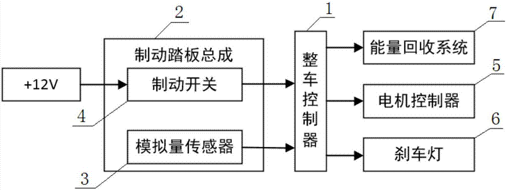
[0018] combine figure 1 As shown, a method for analyzing the brake pedal signal of an electric vehicle includes a vehicle controller 1, the vehicle controller 1 is connected to the output end of the analog sensor 3 of the brake pedal assembly 2, and the vehicle controller 1 is connected to the output end of the brake switch of the brake pedal assembly 2, and the output end of the vehicle controller 1 is respectively connected to the input ends of the ...


PUM


Abstract

The invention relates to the technical field of automobile braking and aims to provide an electric automobile brake pedal signal analytic method. The analytic method comprises the steps that when a signal output by a brake switch is invalid, a complete vehicle control unit judges that an automobile is in a non-braking state, meanwhile, a voltage value output by an analog quantity sensor is detected to be in a zero potential value range, the complete vehicle control unit judges that the automobile is in a zero potential state, and a received voltage signal is calibrated as a zero potential value; when the signal output by the brake switch is valid, the complete vehicle control unit judges that the automobile is in a braking state, and distributes electric braking torque values to an energy recovery system according to the voltage value output by the analog quantity sensor; and when the signal output by the brake switch is invalid, the voltage value output by the analog quantity sensor is not in the zero potential value range, the complete vehicle control unit judges that a braking system is in a failure state, and the complete vehicle is controlled to start a parking mode. By adopting the method, the energy recovery efficiency is improved, and accurate determining of output failures is achieved.

Description

technical field [0001] The invention relates to the technical field of automobile braking, in particular to a method for analyzing brake pedal signals of an electric automobile. Background technique [0002] For the hydraulic braking system, since the production consistency of the pure electric vehicle braking system is difficult to guarantee, it is difficult to maintain the same brake pedal stroke of each vehicle, so the initial zero-angle output voltage of the brake pedal of each electric vehicle is inconsistent, and at the same time With the operation of the vehicle, the brake pedal stroke of the same vehicle will also change, so the vehicle control program must leave enough brake pedal zero potential interval to maintain the consistency of the vehicle control program. Since enough zero potential intervals must be left in the vehicle controller program to eliminate the inconsistency of the brake pedal position output angle caused by production consistency and subsequent o...

Claims


Application Information

Patent Timeline
IPC IPC(8): B60L15/28B60Q1/44B60L7/10
CPCB60L7/10B60L15/28B60L2240/42B60Q1/44Y02T10/72
Inventor 朱长明盛旺黄龙
Owner CHENGDU RAJA NEW ENERGY AUTOMOTIVE TECH CO LTD
Learn More