
Adaptive illumination optimization method applicable to multi-reflection scene

An optimization method, an adaptive technology, applied in the field of adaptive optics, which can solve the problems of adverse effects of decision-making and execution, unsuitable for industrial automation, not universal, etc., to meet the requirements of low-cost system construction, avoid adverse effects, and universality. The effect of suitability

Inactive Publication Date: 2017-11-10
TIANJIN UNIV
View PDF4 Cites 5 Cited by
  • Summary
  • Abstract
  • Description
  • Claims
  • Application Information

AI Technical Summary

Problems solved by technology

[0002] For an 8-bit digital camera, when the measured scene has different parts with high reflectivity and low reflectivity, the captured image only contains 8-bit limited pixel information. If the exposure is increased to make the part with low reflectivity clear, and The part with high reflectivity becomes saturated; conversely, if the exposure is reduced, the part with high reflectivity becomes clear, while the part with low reflectivity becomes dark, so the part with high reflectivity or low reflectivity will appear extremely bright under certain lighting conditions. Bright or extremely dark areas cause loss of pixel information, which has an extremely adverse impact on subsequent decision-making and execution
[0003] Traditional methods mostly use manual adjustment of lighting equipment brightness to avoid overexposure. However, this manual adjustment method is not suitable for industrial automation and is not universal

Method used


Image

  • Adaptive illumination optimization method applicable to multi-reflection scene
  • Adaptive illumination optimization method applicable to multi-reflection scene
  • Adaptive illumination optimization method applicable to multi-reflection scene

Examples


Embodiment Construction

[0022] Below in conjunction with accompanying drawing and specific example the present invention will be further described;

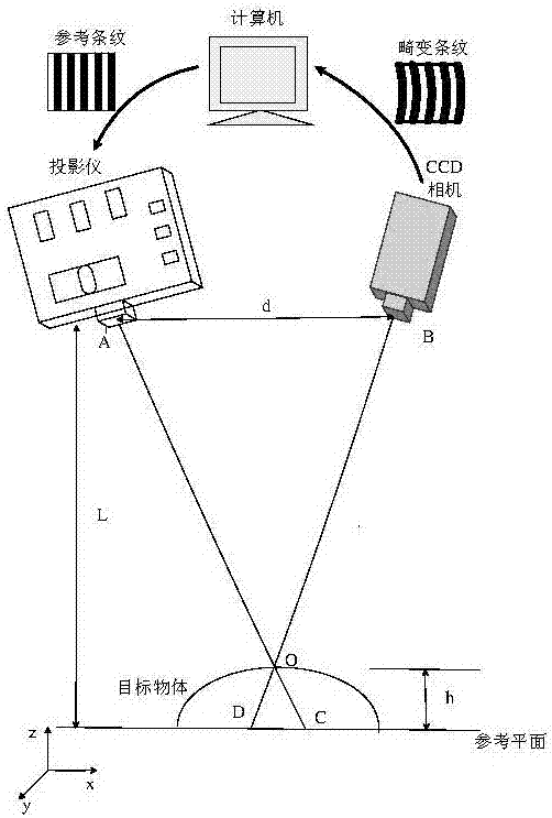
[0023] figure 1 Shown is a schematic diagram of the adaptive lighting device of the present invention. Among them, the projector and the camera adopt a non-coaxial configuration, the distance between the projector and the camera is d, the distance from the projector to the reference plane is L, and the depth of the observation point O is h. Using the triangular similarity principle, the relationship between object depth and fringe phase change is deduced as

[0024]

[0025] Represents the phase change, with

[0026]

[0027] Substituting formula (2) into formula (1), we get

[0028]

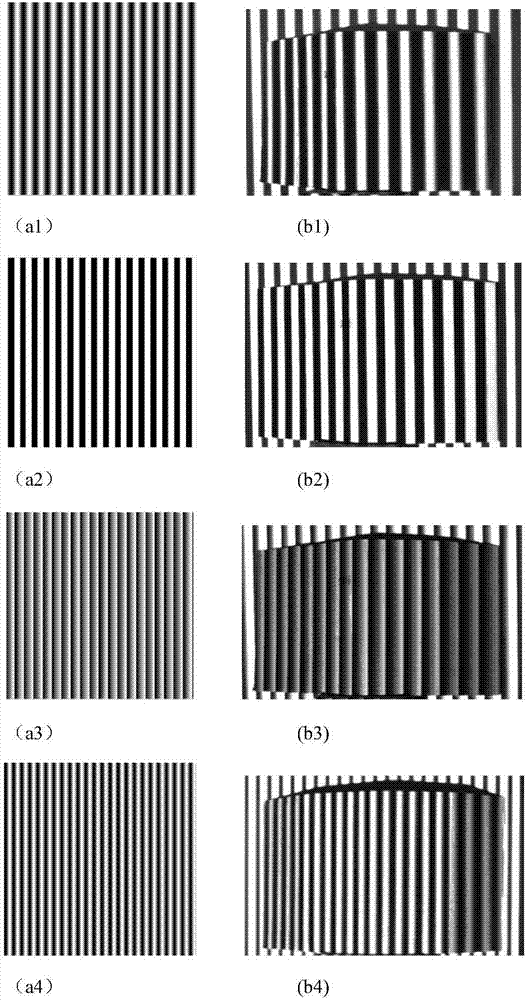
[0029] figure 2 Shown are four reference grating patterns and corresponding distorted grating patterns in the present invention. computer generated as figure 2 The sinusoidal, rectangular, triangular, and dual-frequency sinusoidal grating fringes shown ...


PUM


Abstract

The invention discloses an adaptive illumination optimization method applicable to a multi-reflection scene. The adaptive illumination optimization method applicable to a multi-reflection scene comprises steps of using a projector to project four kinds grating stripes of a sine, a rectangle, a triangle and a double-frequency sine to a surface of a three-dimensional object, wherein the four kinds of grating stripes are four set of reference stripes, obtaining corresponding four sets of distorted stripes, wherein the distorted stripes are obtained by the reference stripes which are modulated by a depth of a three-dimensional object, using Fourier transform to respectively extract fundamental frequency components of four pairs of distorted stripes and reference stripes from a frequency domain, converting a folding phase which is not continuously distributed to a decompressed phase which is continuously distributed in a space through a phase decompression algorithm, establishing pixel matching between a projector and a camera, projecting a processed image to a surface of a three-dimensional target object through inverse proportion light compensation of the projector, choosing an iteration image result having a best effect for each different kind of grating projection and performing comparison of numbers of darkness / saturation pixel on four obtained adaptive illumination images to choose an optimized adaptive illumination method.

Description

technical field [0001] The invention relates to an adaptive lighting optimization method applicable to multi-reflection scenes, belonging to the field of adaptive optics; Background technique [0002] For an 8-bit digital camera, when the measured scene has different parts with high reflectivity and low reflectivity, the captured image only contains 8-bit limited pixel information. If the exposure is increased to make the part with low reflectivity clear, and The part with high reflectivity becomes saturated; conversely, if the exposure is reduced, the part with high reflectivity becomes clear, while the part with low reflectivity becomes dark, so the part with high reflectivity or low reflectivity will appear extremely bright under certain lighting conditions. Bright or extremely dark areas cause the loss of pixel information, which has an extremely adverse impact on subsequent decision-making and execution. [0003] Traditional methods mostly use manual adjustment of ligh...

Claims


Application Information

Patent Timeline
IPC IPC(8): G01B11/25
CPCG01B11/25
Inventor 吕辰刚高爽方干张帅鲍志强
Owner TIANJIN UNIV
Learn More