
Automatic water leakage protection valve

A water leakage protection and valve body technology, applied in valve details, valve device, valve shell structure, etc., can solve the problems of water pipe burst, difficult installation, and inability to play a role in water leakage protection, and achieve the effect of accurate quantitative and easy installation.

Inactive Publication Date: 2017-11-10
XIAMEN EASO CO LTD
View PDF6 Cites 3 Cited by
  • Summary
  • Abstract
  • Description
  • Claims
  • Application Information

AI Technical Summary

Problems solved by technology

Household water often encounters sudden bursting of water pipes or forgetting to turn off the water valve, especially when the user is not on site and cannot deal with it immediately, which will cause serious waste of water resources and economic damage. To solve this problem, there are some electronic water leakage protection valves and ordinary water leakage protection valves on the market. Water leakage protection valve, electronic water leakage protection valve is installed in a water environment, and electronic components are prone to failure, which affects the reliability and service life of the device; while ordinary water leakage protection valves mainly use counterweight or self-weight to automatically cut off the waterway, so it is necessary for The installation position of the protection valve has high requirements, and the installation is difficult. If the installation position is tilted, the function of automatically cutting off the waterway will fail, and it will not be able to protect the water leakage. Deficiency and inconvenience, in-depth conception, and active research and improvement to develop and design the present invention

Method used


Image

  • Automatic water leakage protection valve
  • Automatic water leakage protection valve
  • Automatic water leakage protection valve

Examples


Embodiment Construction

[0025] The present invention will be described in detail below in conjunction with the accompanying drawings and specific implementation.

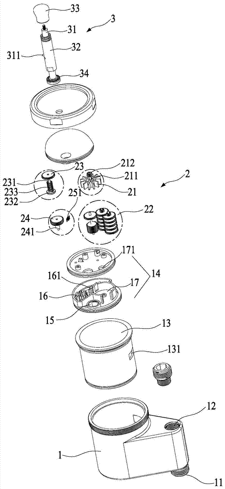
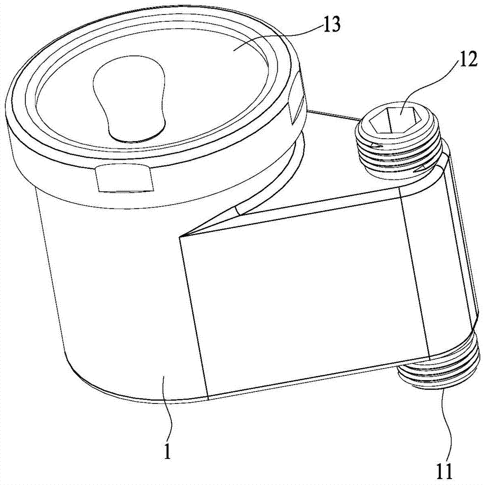
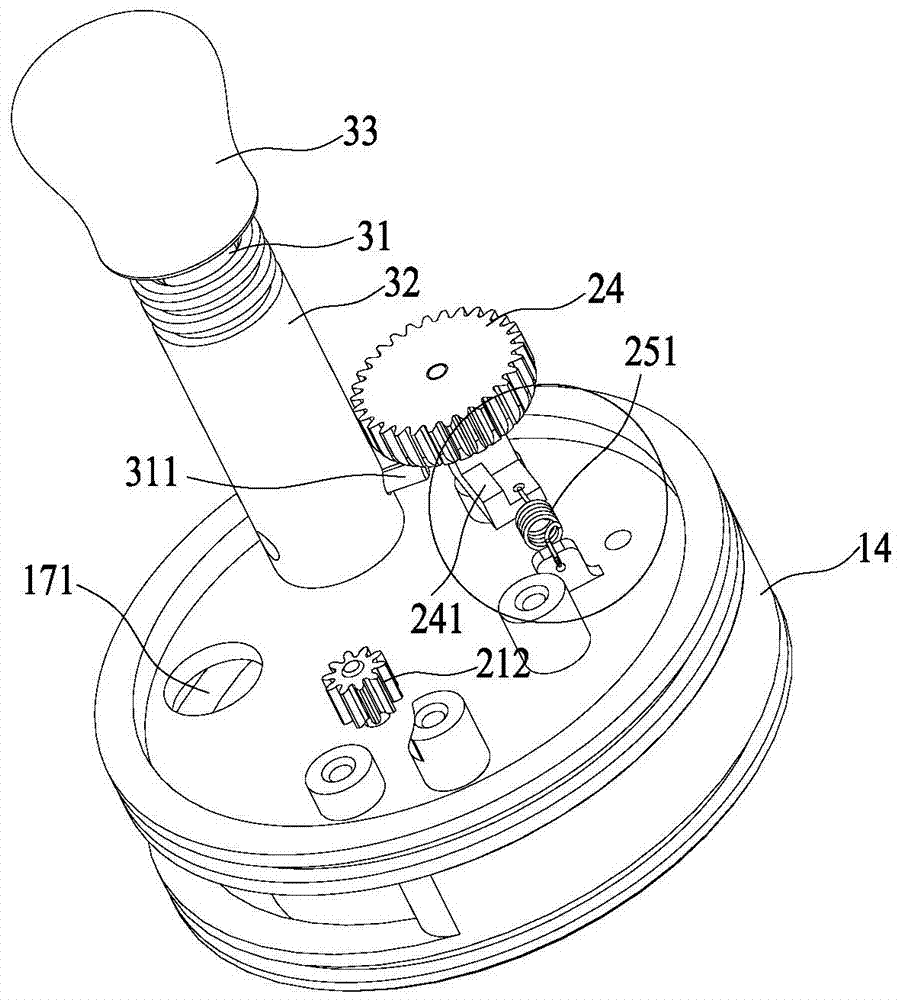
[0026] Such as Figure 1 to Figure 10 As shown, an automatic water leakage protection valve of the present invention includes a valve body 1, a trigger mechanism 2 arranged on the valve body 1, and an on-off assembly 3 for switching on and off the water circuit of the valve body 1;

[0027] The valve body 1 is provided with a water inlet 11 and a water outlet 12, and an inner cavity 13 is formed, and an intermediate cavity 14 is separated in the inner cavity 13, thereby separating the inner cavity 13 into upper and lower parts. The bottom of the cavity 13 is provided with a water hole 15 communicating with the water inlet 11. After the water enters the water hole 15 through the water inlet 11, it communicates with the water outlet 12 through the intermediate cavity 14. A water outlet is provided at intervals in the intermediate cavity 14. ...


PUM


Abstract

The invention discloses an automatic water leakage protection valve which comprises a valve body, a triggering mechanism arranged on the valve body, and a connecting and disconnecting assembly making a valve body water way connected and disconnected. The valve body is provided with a water inlet and a water outlet. The triggering mechanism comprises an impeller, a reduction gear mechanism set, a clutch gear, a swing arm gear and a reset assembly. The impeller drives the reduction gear mechanism set. The clutch gear is engaged with the reduction gear mechanism set and is selectively engaged or disengaged with the swing arm gear. When the swing arm gear is engaged with the clutch gear and rotates to the limit, the connecting and disconnecting assembly is triggered to disconnect the valve body water way. When the swing arm gear is disengaged with the clutch gear, the swing arm gear rotates reversely to reset under the effect of the reset assembly.

Description

technical field [0001] The invention refers to an automatic water leakage protection valve installed on a fluid pipeline to prevent leakage. Background technique [0002] The contradiction of global water supply is becoming increasingly prominent, and the rational use of water resources is a common concern of all mankind. Household water often encounters sudden bursting of water pipes or forgetting to turn off the water valve, especially when the user is not on site and cannot deal with it immediately, which will cause serious waste of water resources and economic damage. To solve this problem, there are some electronic water leakage protection valves and ordinary water leakage protection valves on the market. Water leakage protection valve, electronic water leakage protection valve is installed in a water environment, and electronic components are prone to failure, which affects the reliability and service life of the device; while ordinary water leakage protection valves m...

Claims


Application Information

Patent Timeline
Patent Type & Authority Applications(China)
IPC IPC(8): F16K21/14F16K27/02F16K31/53
CPCF16K21/14F16K27/02F16K31/53
Inventor 陆海涛李真吴平良陈希敏
Owner XIAMEN EASO CO LTD
Learn More