
Simultaneous ring and double-ring single-conical-surface synchronizer

A technology of synchronous ring and inner cone, which is applied in the field of vehicle transmission, can solve problems such as locking, high cost, and small synchronous capacity of cone angle, so as to avoid gear shift sticking and impact, improve transmission efficiency, and reduce friction loss Effect

Inactive Publication Date: 2017-11-10
江苏持华科技有限公司
View PDF7 Cites 6 Cited by
  • Summary
  • Abstract
  • Description
  • Claims
  • Application Information

AI Technical Summary

Problems solved by technology

[0004] Among the factors affecting the synchronous capacity mentioned above, the smaller the friction cone angle, the greater the synchronous capacity, but if the friction cone angle is too small, the friction cone surface will produce self-locking phenomenon; in addition, increasing the number of friction cone surfaces can also increase the synchronous capacity , such as two-cone and three-cone, but increasing the number of friction surfaces, the structures of synchronous rings, combined teeth, gear hubs, gear sleeves, etc. will become complicated and costly
[0005] At present, for synchronizers carrying high torque, multi-cone surfaces and bonding carbon and paper friction materials are often used to increase the synchronization capacity. Locking between the ring and the gear cone, causing the shift to lock
The reason is that self-locking will occur if the cone angle is too small, and the synchronous capacity is small if the cone angle is too large

Method used


Image

  • Simultaneous ring and double-ring single-conical-surface synchronizer
  • Simultaneous ring and double-ring single-conical-surface synchronizer

Examples


Embodiment Construction

[0031] The following will clearly and completely describe the technical solutions in the embodiments of the present invention. Obviously, the described embodiments are only some of the embodiments of the present invention, rather than all the embodiments. Based on the embodiments of the present invention, all other embodiments obtained by persons of ordinary skill in the art without making creative efforts belong to the protection scope of the present invention.

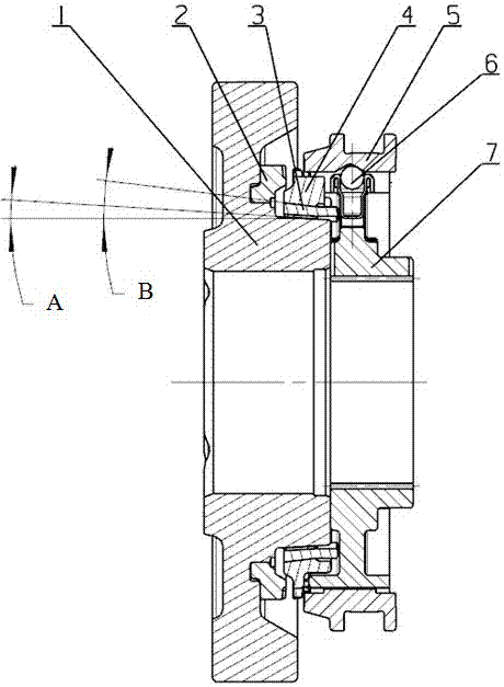
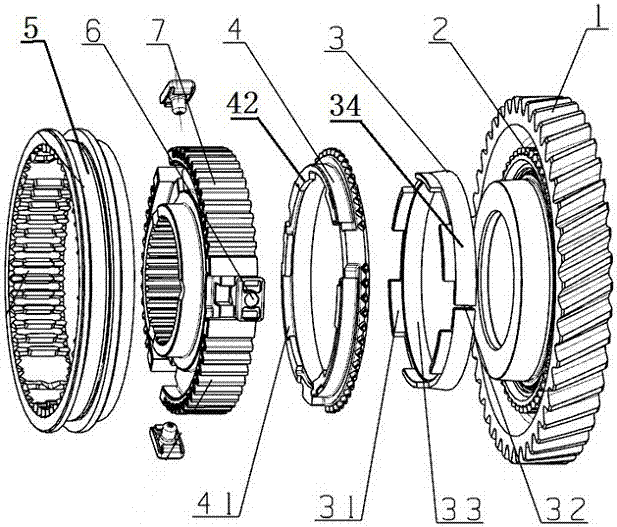
[0032] see figure 1 and figure 2 , the embodiment of the present invention includes:

[0033] A single-ring double-cone synchronizer, comprising: a synchronizer ring, a gear 1, a coupling tooth 2, an adapter sleeve 5, a synchronizer slider 6 and a gear hub 7;

[0034] The gears and the coupling teeth are fixedly connected, and the power is transmitted through the coupling teeth 2 and the gear 1 after shifting. The synchronous ring is set on the coupling teeth and fits with the conical surface between the coupling ...


PUM


Abstract

The invention discloses a simultaneous ring which comprises an outer ring and an inner ring. A plurality of stopping blocks are distributed on the end face, far away from a gear, of the outer ring in the circumferential direction, and a notch is formed between every two adjacent stopping blocks; the inner ring comprises a circular-ring-shaped base provided with an inner conical surface and an outer conical surface, and therefore an inner taper angle A and an outer taper angle B are formed, the value of the inner taper angle A needs to be set to be small, and the value of the outer taper angle B needs to be set to be large; and a plurality of protruding blocks are distributed on the end face, far away from the gear, of the circular-ring-shaped base in the circumferential direction, the multiple protruding blocks are clamped into the multiple notches, the circumferential width of the protruding blocks is smaller than the circumferential width of the notches, and therefore the outer ring is allowed to be rotated by a certain angle relative to the inner ring. The invention further discloses a double-ring single-conical-surface synchronizer with the above simultaneous ring. By means of the simultaneous ring, larger simultaneous capacity can be guaranteed under the condition of one single conical surface, the self-lock adhesion phenomenon can be avoided, impact in the ring pulling process after synchronization is avoided, gear shifting is smooth, manufacturing is convenient, and the production cost is low.

Description

technical field [0001] The invention relates to the technical field of vehicle transmission, in particular to a synchronous ring and a double-ring single-cone synchronizer. Background technique [0002] Synchronizers are set between the gears of the existing transmissions to ensure that the meshing of the gears is not impacted when shifting gears, eliminate the noise of shifting, prolong the life of the gears, and make the shifting process light and fast, which is conducive to improving the performance of automobiles. power and fuel economy. [0003] The synchronizing capacity of the synchronizer directly reflects the synchronizing ability of the synchronizing device. The larger the value, the stronger the synchronizing ability. The main factors affecting the synchronizing capacity are: friction coefficient, friction radius, friction cone angle and the number of friction cone surfaces. [0004] Among the factors affecting the synchronous capacity mentioned above, the smalle...

Claims


Application Information

Patent Timeline
Patent Type & Authority Applications(China)
IPC IPC(8): F16D23/04
CPCF16D23/025F16D23/04
Inventor 蒋文东谢释斋
Owner 江苏持华科技有限公司
Learn More