
Fixing structure of light bars in LED (light-emitting diode) backlight module

A technology of LED light bar and backlight module, which is applied in the field of TV, can solve the problems of complex fixed structure and inconvenient installation, and achieve the effect of simple installation, not easy to slide out, and good contact

Active Publication Date: 2013-12-04
XIAMEN PRIMA TECH
View PDF4 Cites 3 Cited by
  • Summary
  • Abstract
  • Description
  • Claims
  • Application Information

AI Technical Summary

Problems solved by technology

The fixing structure of the LED light bar in the prior art is relatively complicated, which causes inconvenience in installation

Method used


Image

  • Fixing structure of light bars in LED (light-emitting diode) backlight module
  • Fixing structure of light bars in LED (light-emitting diode) backlight module
  • Fixing structure of light bars in LED (light-emitting diode) backlight module

Examples


Embodiment Construction

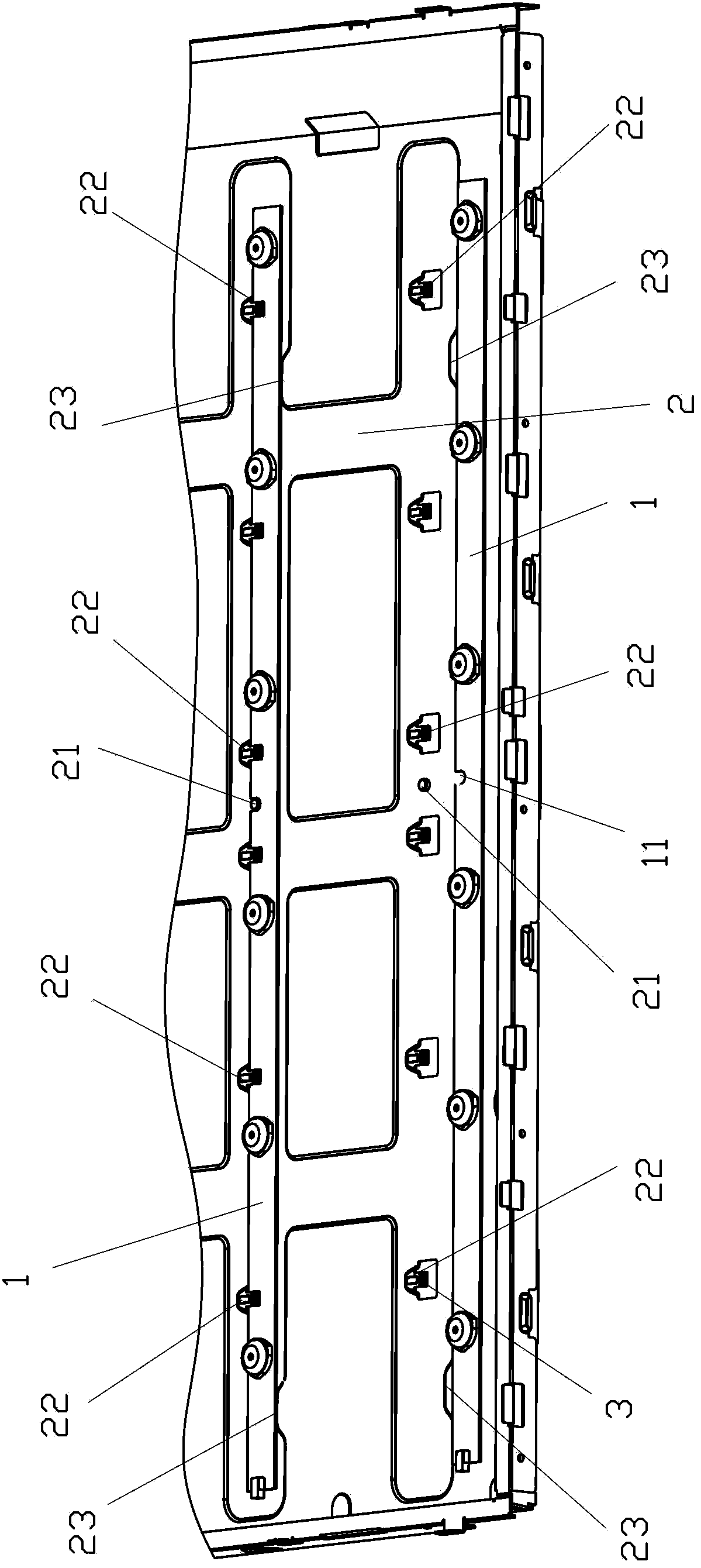
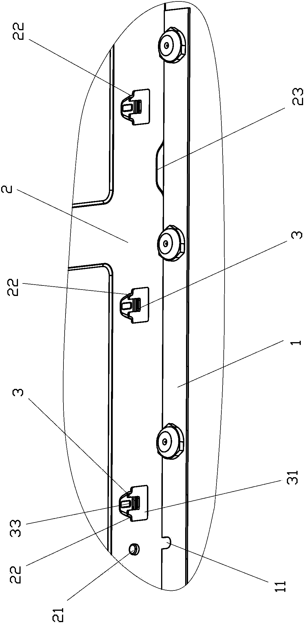
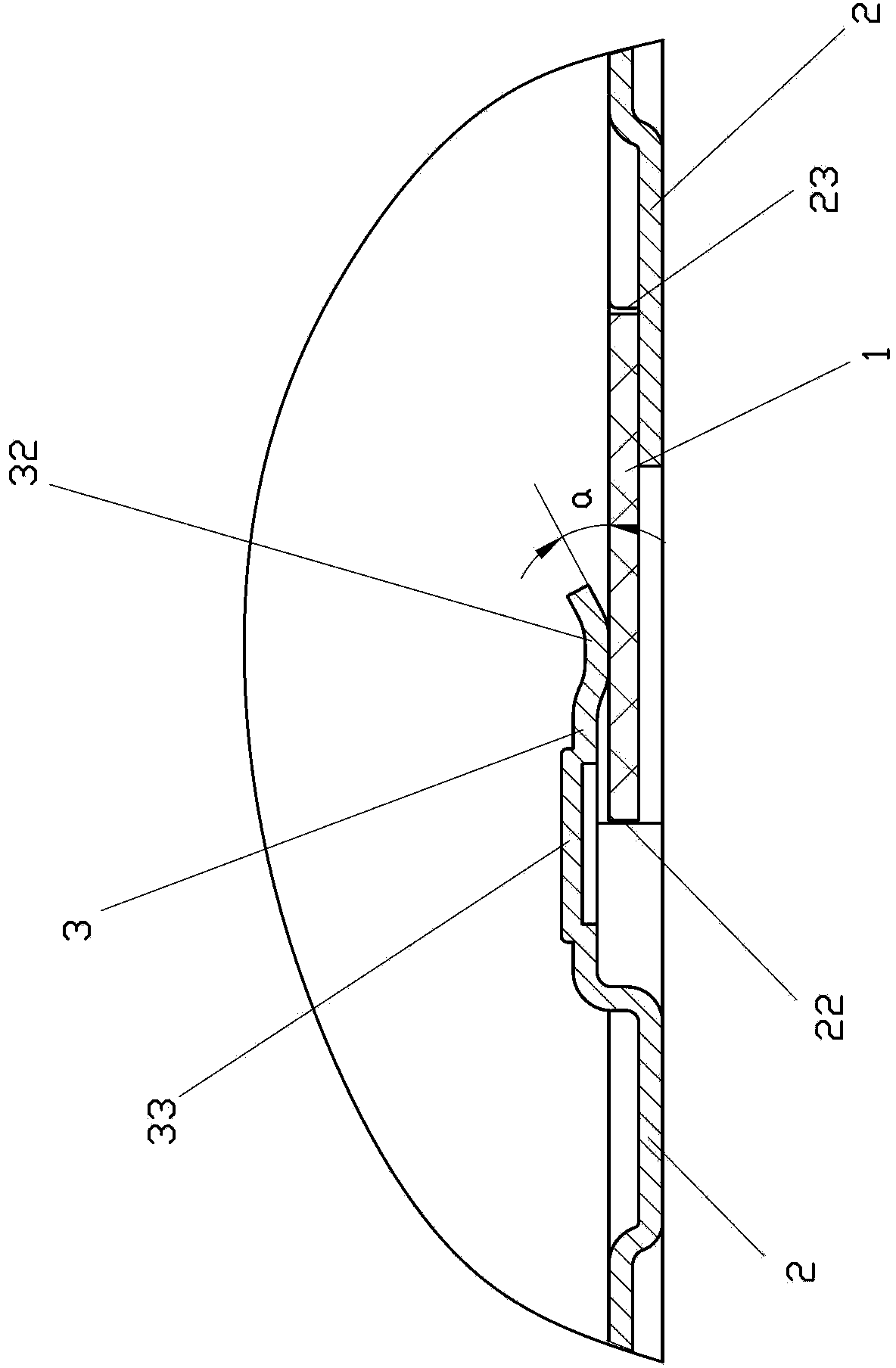
[0019] Examples, see Figure 1 to Figure 3 As shown, the fixing structure of the light bar in a kind of LED backlight module of the present invention comprises:

[0020] The LED light bar PCB board 1, at least one U-shaped groove 11 is provided on the edge of one of the long sides of the LED light bar PCB board 1;

[0021] The hardware backboard 2 is provided with a positioning post 21 formed by stamping and adapted to the U-shaped groove of the LED light bar PCB at the installation place corresponding to the LED light bar PCB board in the hardware backboard 2 . Corresponding to one of the long sides of the LED light bar PCB board, there are several first limiting protrusions 22 formed by stamping, and there are several first limiting convex hulls 22 corresponding to the other long side of the LED light bar PCB board in the hardware backboard. The second limiting convex hull 23 formed by stamping is used, and the two long sides of the LED light strip PCB board respectively ab...


PUM

PropertyMeasurementUnit
Bend angleaaaaaaaaaa

Abstract

The invention discloses a fixing structure of light bars in an LED backlight module. The fixing structure of the light bars in the LED backlight module comprises LED light bar PCBs (Printed circuit boards) and a metal back plate; the LED light bar PCBs are provided with at least one U-shaped groove; the metal back plate is provided with positioning columns which are formed by stamping and used for matching with the U-shaped grooves, and is also provided with a plurality of first limit protrusions and a plurality of second limit protrusions, the first limit protrusions and the second limit protrusions are formed by stamping, two long sides of the LED light bar PCBs abut against the positions of the first limit protrusions and the second limit protrusions to enable the LED light bar PCBs to be clamped between the first limit protrusions and the second limit protrusions, the first limit protrusions are also provided with elastic press pieces to press the surfaces of the LED light bar PCBs towards the large surface of the metal back plate. The fixing structure of the light bars has the advantages of being easy and convenient to install, high in production efficiency, relatively low in costs, accurate and reliable in positioning, not easy to slip off in vibration and drop tests, good in contact between the light bars and the metal back plate and capable of smoothly conducting heat out through the metal back plate.

Description

technical field [0001] The invention relates to the technical field of televisions, in particular to a fixing structure for a light bar in an LED backlight module. Background technique [0002] With the continuous development of TV technology, various ultra-large screens and ultra-thin TVs have come out one after another, and LCD TVs are one of them. LCD TVs have the characteristics of thin body, large screen, no radiation, and high-definition digital display. Features, as a home appliance product has become more and more popular among consumers. With the competition in the TV industry becoming more and more fierce, and the country's requirements for TV energy saving are getting higher and higher, cold cathode luminescent direct-lit LCD TVs (CCFL) have been gradually eliminated by the market, and replaced by medium and high-power LEDs. Direct-lit LCD TVs with light sources are hereinafter referred to as direct-lit LCD TVs. [0003] The backlight module of the direct-lit LE...

Claims


Application Information

Patent Timeline
IPC IPC(8): F21V19/00F21Y101/02
Inventor 洪岩陈云峰杨钦华李淑庄陈光永范秀敏
Owner XIAMEN PRIMA TECH
Learn More