Connecting structure and system of integrated brake device for railway vehicle
A braking device and technology for rail vehicles, applied to the operating mechanism of railway vehicle brakes, braking transmission devices, railway braking systems, etc., can solve the problems of large space occupied by fixed frames, inconvenient maintenance and disassembly of components, etc., and achieve improved Connection stability, simple structure, and design weight reduction effects
- Summary
- Abstract
- Description
- Claims
- Application Information
AI Technical Summary
Problems solved by technology
Method used
Image
Examples
no. 1 example
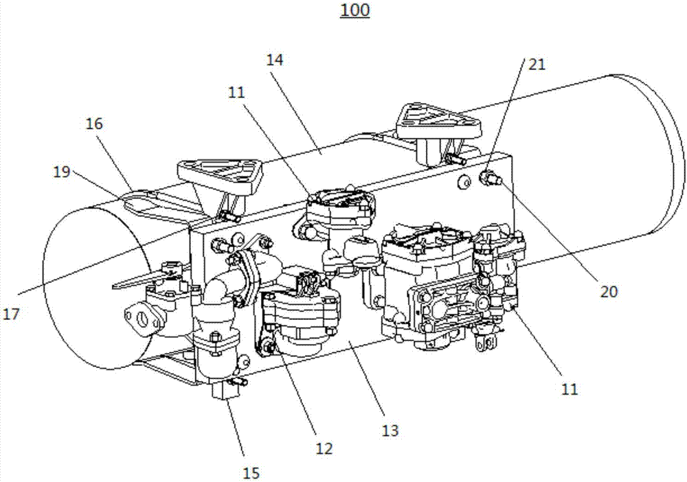
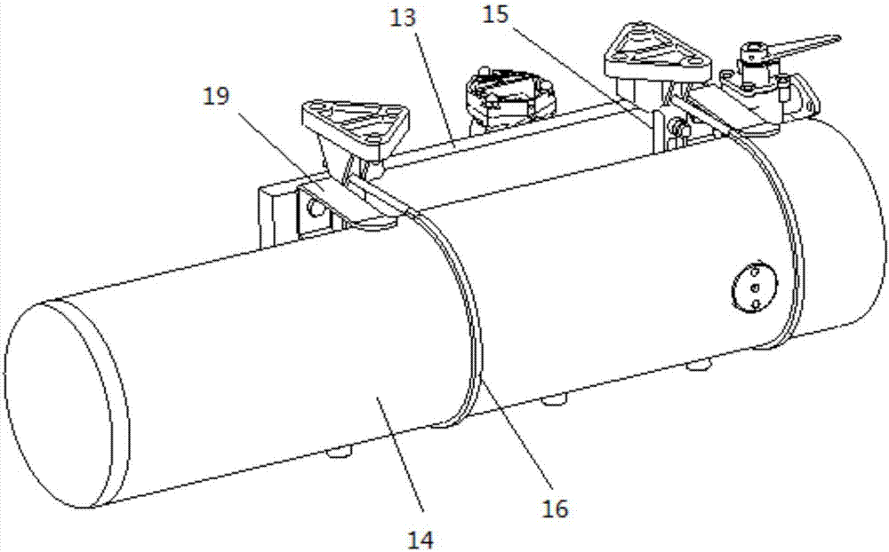
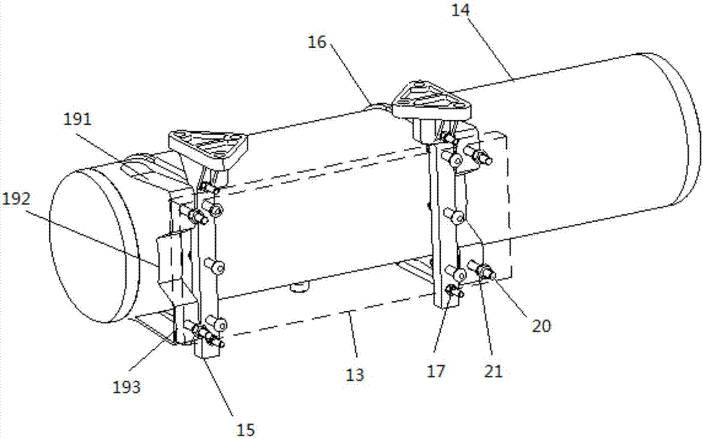
[0036] Please refer to figure 1 , the present embodiment provides a connection structure 100 for an integrated braking device for a rail vehicle, including a brake valve 11, a dust collector 12, an intermediate body 13, an air cylinder 14, a bracket assembly and a connection assembly.
[0037] In this embodiment, the intermediate body 13 is a plate-shaped structure, and the interior of the intermediate body 13 is provided with a chamber and a pipeline. Different types of brake valves 11 and dust collectors 12 are installed on the same side of the intermediate body 13, so that different models The brake valve 11 and the dust collector 12 are centrally arranged on the intermediate body 13, which saves the space occupied by the integrated braking device; the bracket assembly is installed on the side of the intermediate body 13 away from the brake valve 11, and the intermediate body 13 and the air cylinder 14 is detachably connected through the connection assembly, which improves ...
no. 2 example
[0057] After research, the researchers found that the connection structure 100 of the rail vehicle integrated braking device provided by the present invention, on the basis of the above-mentioned first embodiment, can also make the following optional other structural solutions, which are specifically described as follows:
[0058] Such as Figure 4 As shown, the threaded section of the U-shaped cylinder collar 16 includes a first threaded section 161 and a second threaded section 162, the first threaded section 161 is passed through the connecting hole, and the second threaded section 162 is far away from the bracket relative to the first threaded section 161 15 , that is to say, the second threaded section 162 is located at the end of the U-shaped cylinder collar 16 , and the first threaded section 161 is located between the second threaded section 162 and the air cylinder 14 . The first locking nut 17 is located on the first threaded section 161 , and the first locking nut 1...
no. 3 example
[0064] An embodiment of the present invention provides a connection system for an integrated braking device for a rail vehicle, including the connection structure 100 for an integrated braking device for a rail vehicle provided in the above embodiment.
[0065] Please refer to Image 6 , in this embodiment, in order to facilitate the connection of the connection structure 100 of the integrated braking device for rail vehicles with the body of the rail vehicle or other connecting parts 25, the connection system of the integrated braking device for rail vehicles includes a bracket mounting seat 23, The bracket mounting seat 23 is integrally formed with the bracket 15 . Such as Figure 7 As shown, when the connection structure 100 of the rail vehicle integrated braking device is connected to the rail vehicle body or other connection components 25, at least four The detachment-preventing hook 24 can add a detachment-preventing function to the connection of the connection structu...
PUM
 Abstract
Description
Claims
Application Information
 - R&D Engineer
- R&D Manager
- IP Professional
- Industry Leading Data Capabilities
- Powerful AI technology
- Patent DNA Extraction
Browse by: Latest US Patents, China's latest patents, Technical Efficacy Thesaurus, Application Domain, Technology Topic, Popular Technical Reports.
© 2024 PatSnap. All rights reserved.Legal|Privacy policy|Modern Slavery Act Transparency Statement|Sitemap|About US| Contact US: help@patsnap.com


