
Method of optimizing sar antenna pattern test

An antenna pattern and pattern technology, applied in the field of optimization, can solve the problem of long test time, and achieve the effect of speeding up the development progress and shortening the test time.

Active Publication Date: 2019-08-30
SHANGHAI SATELLITE ENG INST
View PDF3 Cites 6 Cited by
  • Summary
  • Abstract
  • Description
  • Claims
  • Application Information

AI Technical Summary

Problems solved by technology

[0003] The technical problem to be solved by the present invention is to provide a method for optimizing the SAR antenna pattern test, which solves the time-consuming problem of the radar satellite SAR antenna pattern ground test, accelerates the progress of satellite development; provides a certain reference

Method used


Image

  • Method of optimizing sar antenna pattern test
  • Method of optimizing sar antenna pattern test
  • Method of optimizing sar antenna pattern test

Examples


Embodiment Construction

[0017] The preferred embodiments of the present invention are given below in conjunction with the accompanying drawings to describe the technical solution of the present invention in detail.

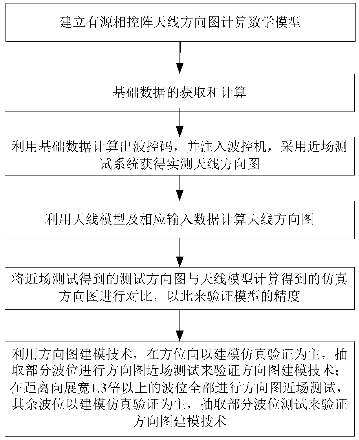
[0018] Such as figure 1 As shown, the method for optimizing the SAR antenna pattern test of the present invention comprises the following steps:

[0019] Step 1. First, establish the mathematical model for calculating the pattern of the active phased array antenna according to the electromagnetic field theory; the formula of the mathematical model for calculating the pattern of the active phased array antenna is shown in formula (1):

[0020]

[0021] in:

[0022] f mn is the electric field pattern of the antenna unit;

[0023] I mn is the amplitude excitation (amplitude distribution) of the antenna element;

[0024] A mn Amplitude errors due to feed network and components;

[0025] alpha mn is the failure factor of the antenna unit, and its value is only 0 or 1 (0 means failu...


PUM


Abstract

The invention discloses a method for optimizing an SAR antenna directional diagram test. The method includes the steps of establishing an active phased array antenna directional diagram calculating mathematics model according to the electromagnetic field theory, obtaining and calculating basic data of an active phased array antenna, calculating and storing all wave position antenna amplitude phase weight coefficients of the SAR antenna according to the design requirement and engineering realizability, and using a near-field test method to obtain antenna sub-array directional diagrams at different positions of an antenna array plane under a planar near-field test system environment. The test time of an SAR antenna directional diagram test is greatly shortened, the satellite development progress is ensured and accelerated and a reference is provided for test SAR antenna directional diagram of subsequent radar satellite models.

Description

technical field [0001] The invention relates to an optimization method, in particular to a method for optimizing the SAR antenna pattern test. Background technique [0002] With the rapid development of Synthetic Aperture Radar (SAR), my country's first high-resolution X-band active planar phased array SAR satellite came into being. The satellite has right-view and left-view imaging capabilities, and there are four working modes in each side-view state. The antenna beams of the spotlight mode and the scanning mode not only need to change the angle of view in the range direction, but also need to scan in the azimuth direction. Due to the coupling of the range direction and the azimuth direction, the wave number in these two modes is equal to the multiplication of the wave number in the range direction. The number of wave positions in the azimuth direction increases significantly; in order to make the target located in the center of the imaging zone as much as possible, the o...

Claims


Application Information

Patent Timeline
Patent Type & Authority Patents(China)
IPC IPC(8): G01R29/10
Inventor 庄磊叶兴彬张久玲张一夫朱鸿昌范季夏
Owner SHANGHAI SATELLITE ENG INST
Learn More