Arch-shaped counterfort vertical quay structure

An upright and arched technology, which is used in quay walls, water conservancy projects, marine engineering, etc., can solve the problems of poor economy, poor structural stability, and large fore-toe stress of buttressed structures, and achieves simple construction, lightweight structure, enhanced strength and so on. adaptive effect

Pending Publication Date: 2017-11-07
CCCC THIRD HARBOR CONSULTANTS
View PDF7 Cites 1 Cited by
  • Summary
  • Abstract
  • Description
  • Claims
  • Application Information

AI Technical Summary

Problems solved by technology

[0002] The general wharf structure with buttress structure is subject to many limitations due to its own structural stress, large front toe stress, and poor structural stability.
The vertical earth pressure distribution behind the buttressed wharf structural wall first increases with the increase of the covering soil depth, but after a certain depth, with the increase of the covering soil layer thickness, the earth pressure needs to be increased by increasing the section size, increasing the vertical plate and Only the thickness of the ribs and the reinforcement of the section can meet the stress requirements of the structural calculation, resulting in poor economical efficiency of the buttress structure, which has no advantages in the comparison and selection of structural schemes

Method used


Image

  • Arch-shaped counterfort vertical quay structure
  • Arch-shaped counterfort vertical quay structure

Examples


Embodiment Construction

[0017] The preferred embodiments of the present invention are given below in conjunction with the accompanying drawings to describe the technical solution of the present invention in detail.

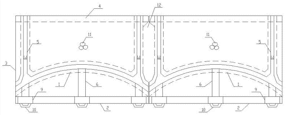
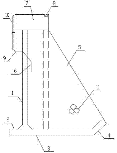
[0018] Such as Figure 1 to Figure 2 As shown, the arched buttress vertical wharf structure of the present invention includes a vertical plate 1, a front toe plate 2, an inner bottom plate 3, a tail plate 4, a rib plate 5, a corbel 6, a guide beam 7, a steel rail 8, and a berth member 9 , fender 10, backfill 11, filter well 12, the ribs are located on the inner side of the vertical plate 1, the front toe plate 2 and the inner bottom plate 3 are all located on the bottom of the vertical plate 1, the front toe plate 2, the inner bottom plate 3, The ribs 5 are all connected to the stern plate 4, the guide beam 7 is located on the top of the vertical plate 1, the ship member 9 and the fender 10 are located on one side of the corbel 6, and the middle of the corbel 6 and the vertical plate 1 i...


PUM


Abstract

The invention discloses an arch-shaped counterfort vertical quay structure. The arch-shaped counterfort vertical quay structure comprises a vertical plate, a front toe board, an inner bottom plate, a tail plate, a ribbed plate, a bracket, a guide beam, a steel rail, a berthing member, a fender, backfill and a reverse filtering well. The ribbed plate is located on the inner side of the vertical plate. The front toe board and the inner bottom plate are both located at the bottom end of the vertical plate. The front toe board, the inner bottom plate and the ribbed plate are all connected with the tail plate. The guide beam is located at the top end of the vertical plate. The berthing member and the fender are both located on one side of the bracket. The bracket is fixed to the middle of the vertical plate, the steel rail is located at the top end of the guide beam, the backfill is located on the ribbed plate, and the reverse filtering well is located on the outer side of the ribbed plate. The arch-shaped counterfort vertical quay structure can adapt to rebuilt or newly-built large quay projects on complex conditions, especially large quays on open seas. The arch-shaped counterfort vertical quay structure has the beneficial effects that the structure is light and ingenious and materials are saved. The combination structure composed of the arch-shaped vertical plate and the ribbed plate, the stress form of an existing product is changed, the beneficial effects that the rigidity is large and the bending resistance is high are achieved, and the quay level and the structure resistance can be further improved.

Description

technical field [0001] The invention relates to engineering fields such as water conservancy, roads, slope protection, roadbeds, filling retaining walls, and landscape design trails, and in particular relates to an arched buttress vertical wharf structure. Background technique [0002] Generally, buttress-type wharf structures are subject to many limitations due to their own structural stress, large front toe stress, and poor structural stability. The vertical earth pressure distribution behind the buttressed wharf structural wall first increases with the increase of the covering soil depth, but after a certain depth, with the increase of the covering soil layer thickness, the earth pressure needs to be increased by increasing the section size, increasing the vertical plate and The stress requirements of structural calculations can only be met by the thickness of the ribs and the increase of cross-section reinforcement, which leads to poor economical efficiency of the butt...

Claims


Application Information

Patent Timeline
Patent Type & Authority Applications(China)
IPC IPC(8): E02B3/06
CPCE02B3/068
Inventor 李增光朱林祥高莹李嘉隆郜卫东吴辉尤坛洪
Owner CCCC THIRD HARBOR CONSULTANTS
Why Eureka
Try Eureka