Machining clamp with adjustable direction

A mechanical processing and adjustable technology, applied in the direction of manufacturing tools, metal processing equipment, metal processing machinery parts, etc., can solve problems such as affecting the scope of use, inability to apply the workpiece clamping datum, and inability to achieve specific adjustment of the clamp.

Inactive Publication Date: 2017-11-07
王佳庆
View PDF1 Cites 12 Cited by
  • Summary
  • Abstract
  • Description
  • Claims
  • Application Information

AI Technical Summary

Problems solved by technology

[0002] The processing fixture is used to fix the processing object and make it occupy the correct position in the process of mechanical manufacturing, which is convenient for construction or inspection. With the maturity of mechanical processing technology in China, various mechanical processing equipment has developed rapidly, and the style of processed workpieces has also changed. More and more, and the existing mechanical fixtures are relatively fixed, so it will affect its scope of use to a certain extent. Changing fixtures during processing will also reduce processing efficiency and increase labor intensity and inconvenience for workers. The patent with publication number 201621362486.4 discloses a mechanical processing fixture with adjustable direction, including a processing table, two sets of sliding rails are arranged on both sides of the upper surface of the processing table, and a sliding support plate for sliding connection is provided on each group of sliding rails , and the lower surface of the sliding support plate is provided with a first sliding groove corresponding to the sliding track; The sliding track can adjust the left and right direction of the fixture, but in the process of using the above patents, the adjustment of the angle direction of the fixture body cannot be realized, and it cannot be applied to the situation where the workpiece clamping reference plane is different, and the positioning connection between the fixture body and the machine tool body cannot be realized.

Method used


Image

  • Machining clamp with adjustable direction
  • Machining clamp with adjustable direction
  • Machining clamp with adjustable direction

Examples


Embodiment Construction

[0018] The following will clearly and completely describe the technical solutions in the embodiments of the present invention with reference to the accompanying drawings in the embodiments of the present invention. Obviously, the described embodiments are only some, not all, embodiments of the present invention. Based on the embodiments of the present invention, all other embodiments obtained by persons of ordinary skill in the art without making creative efforts belong to the protection scope of the present invention.

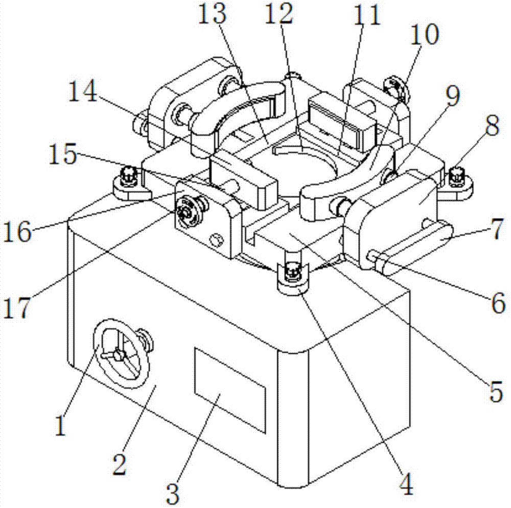
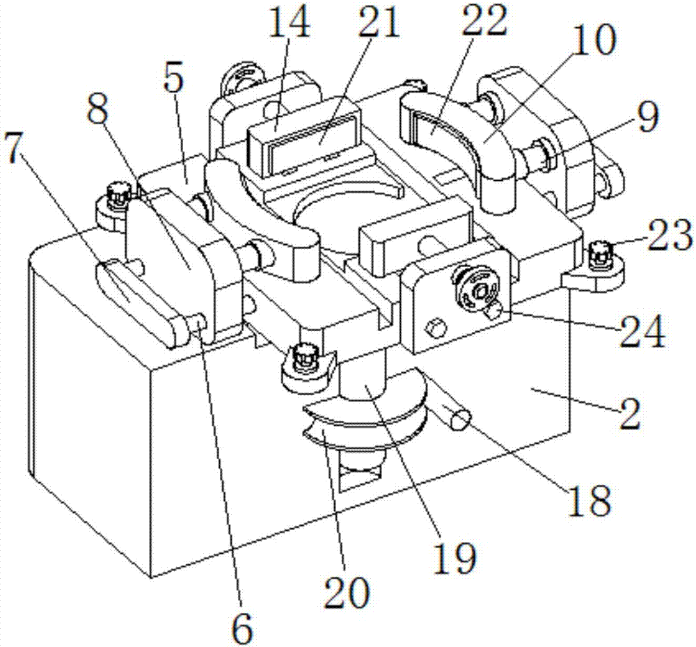
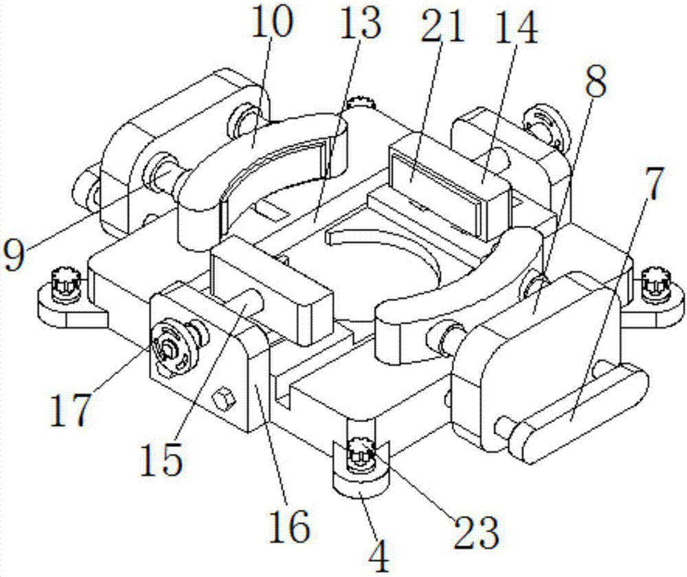
[0019] see Figure 1-4 , the present invention provides a technical solution: a mechanical processing fixture with adjustable direction, including a machine tool body 2, a clamp body 5 is provided on the upper side of the machine tool body 2, and two groups of slides symmetrically distributed are arranged on both sides of the clamp body 5. The shaft 6, the end of the sliding shaft 6 far away from the clamp body 5 is connected with a baffle 7, the middle positi...


PUM


Abstract

The invention discloses a machining fixture with adjustable direction, which comprises a machine tool body, a clamp body is arranged on the upper side of the machine tool body, and one end of a spindle is connected to the side of the clamp body close to the machine tool body. The other end extends to the inside of the main body of the machine tool and is connected to the main body of the machine tool through a bearing. A worm gear is provided in the middle of the main shaft, and a worm is connected to the side of the main body of the machine tool close to the worm wheel through a bearing, and the worm is connected with the worm gear. , one end of the worm extends to the outside of the main body of the machine tool and is connected with a runner, the adjustment of the angle direction of the chuck body can be realized through the runner, worm, main shaft and worm wheel, the arc-shaped fixing plate has a rectangular positioning groove, an arc-shaped positioning groove and The rectangular fixed plate can be applied to the situation where the workpiece clamping reference plane is different, and the fixed anti-skid plate and the positioning ring boss can realize the positioning connection between the clamping body and the main body of the machine tool.

Description

technical field [0001] The invention relates to the technical field of machining fixtures, in particular to a machining fixture whose direction can be adjusted. Background technique [0002] The processing fixture is used to fix the processing object and make it occupy the correct position in the process of mechanical manufacturing, which is convenient for construction or inspection. With the maturity of mechanical processing technology in my country, various mechanical processing equipment has developed rapidly, and the style of processed workpieces has also changed. More and more, and the existing mechanical fixtures are relatively fixed, so it will affect its scope of use to a certain extent. Changing fixtures during processing will also reduce processing efficiency and increase labor intensity and inconvenience for workers. The patent with publication number 201621362486.4 discloses a mechanical processing fixture with adjustable direction, including a processing table, tw...

Claims


Application Information

Patent Timeline
Patent Type & Authority Applications(China)
IPC IPC(8): B23Q3/06
CPCB23Q3/06
Inventor 王佳庆
Owner 王佳庆
Why Eureka
Try Eureka