Tube distributing structure of lateral steam feeding condenser

A technology of condenser and steam inlet, which is used in steam/steam condensers, lighting and heating equipment, etc. It can solve the problems of unsuitable dual-process or smaller condensers, small high-speed diffusion section of tube bundles, and insufficiently compact structure. , to reduce the resistance, improve the pipe layout rate, and improve the heat exchange efficiency.

Active Publication Date: 2017-10-27
HANGZHOU GUONENG STEAM TURBINE ENGINEER
View PDF7 Cites 5 Cited by
  • Summary
  • Abstract
  • Description
  • Claims
  • Application Information

AI Technical Summary

Problems solved by technology

[0005] In the above two methods, one is arranged with the axis of the diffusion tank at 30°, and the other is arranged with the axis of the diffusion tank at 60°, and the adjacent pipes are arranged in an equilateral triangle, which is inconsistent with the diffusion angle (10-15°) of the exhaust steam, and the formed tube bundle is high-speed The diffusion cross section is small, the exhaust resistance is relatively large, and the arrangement of the exhaust port is complex, which increases the exhaust resistance
The shape of the tube bundle formed, or the structure is not compact enough ( image 3 structure shown), or not suitable for the needs of double-pass or smaller condensers ( Figure 4 structure shown)

Method used


Image

  • Tube distributing structure of lateral steam feeding condenser
  • Tube distributing structure of lateral steam feeding condenser
  • Tube distributing structure of lateral steam feeding condenser

Examples


Embodiment Construction

[0019] The present invention will be further described below in conjunction with the accompanying drawings and examples.

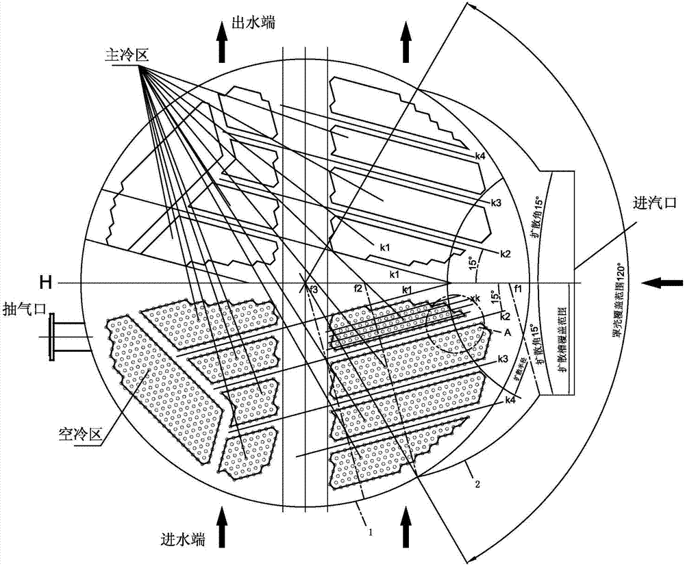
[0020] In this embodiment, 2220 tubes of 20 mm are arranged in the cavity of the condenser with a diameter of 2000 mm, the distance between the tubes is 30 mm, and the two ends of all the tubes are respectively fixed on the tube sheets at both ends of the condenser.

[0021] In the pipe layout structure of the side steam inlet condenser provided by the present invention, the steam inlet of the condenser is located at the right end of the condenser, and several tube bundles ( figure 1 , figure 2 In , each tube bundle is surrounded by a thick double-dot dash line, which contains multiple tubes; for the sake of clarity, some tube bundles are only drawn with thick double-dot dash lines, and the tubes in them are omitted), and the diffusion between the tube bundles is to facilitate the circulation of steam The axes of the adjacent diffuser grooves are all ar...


PUM


Abstract

The invention relates to an arrangement structure for heat exchange tubes of a lateral steam feeding condenser for an axial steam discharging turbine, and aims to provide an improved tube distributing structure of a lateral steam feeding condenser. More heat exchange tubes can be arranged in a tube plate range with the same size, or under the conditions that the size of the condenser is the same and the number of the heat exchange tubes is also the same, the steam discharging resistance is lower, the steam discharging condensing effect is better, the lateral steam feeding condenser can run under the designed vacuum pressure, and the heat exchange efficiency of the lateral steam feeding condenser is guaranteed. According to the technical scheme, the tube distributing structure of the lateral steam feeding condenser comprises a plurality of tube bundles which are positioned in a cavity of the condenser, diffusion grooves which facilitates circulation of steam are formed among the tube bundles, and the axes of the adjacent diffusion grooves are arranged in parallel. The improved tube distributing structure of the lateral steam feeding condenser is characterized in that an included angle between the axis of each diffusion groove and the transverse central line of the condenser is 10-15 degrees so as to be matched with a diffusion angle of steam fed into an air inlet at the right end of the condenser.

Description

technical field [0001] The invention relates to an arrangement structure of heat exchange tubes for a side-to-side steam inlet condenser of an axial exhaust steam turbine, in particular to a low steam exhaust resistance and compact structure suitable for steam turbine exhaust to enter the condensing steam from the side The layout structure of the heat exchange tubes (hereinafter referred to as tubes) of the device. Background technique [0002] With the increasing demand for waste heat utilization and biomass power generation and other low calorific value steam-driven steam turbines, the use of axial exhaust steam turbines in devices is becoming more and more extensive, and the use of side steam-inlet condensers for them is also increasing. more and more. The quality of the steam used by the axially exhausted steam turbine is relatively low. In order to make full use of the thermal performance of the low-quality steam, the exhaust steam resistance of the condenser is requir...

Claims


Application Information

Patent Timeline
Patent Type & Authority Applications(China)
IPC IPC(8): F28B1/02F28B9/00
CPCF28B1/02F28B9/00
Inventor 董晨
Owner HANGZHOU GUONENG STEAM TURBINE ENGINEER
Why Eureka
Try Eureka