
Pump motor with A isolation tank

A pump motor, isolation tank technology, applied in the direction of pumps, parts of pumping devices for elastic fluids, pump devices, etc., can solve problems such as the limitation of the possibility of pump use

Active Publication Date: 2017-10-27
BUHLER MOTOR GMBH
View PDF9 Cites 6 Cited by
  • Summary
  • Abstract
  • Description
  • Claims
  • Application Information

AI Technical Summary

Problems solved by technology

As only a relatively small surface area is available for heat transfer, only a limited heat removal power can be produced, so the possibilities for use of the pump are limited

Method used


Image

  • Pump motor with A isolation tank
  • Pump motor with A isolation tank
  • Pump motor with A isolation tank

Examples


Embodiment Construction

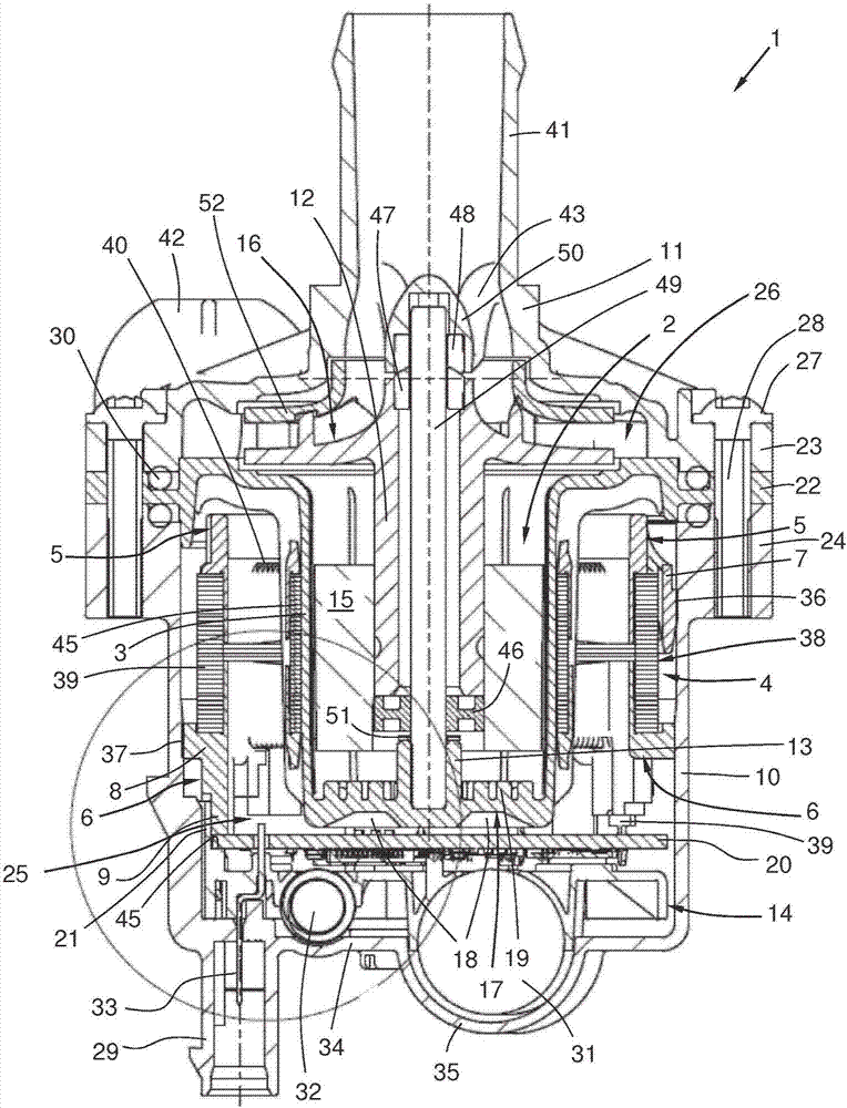
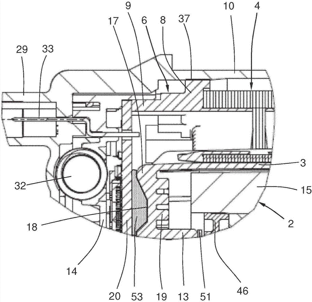
[0020] figure 1 A sectional view of a pump motor 1 according to the invention is shown with a wound stator 4 , a permanent magnet rotor 2 , an insulating pot 3 , a pump head 11 , a circuit board 20 , a carrier plate 14 and a motor housing 10 . The stator 4 , the circuit board 20 and the carrier plate 14 are located in the dry chamber 25 . The permanent magnet rotor 2 is mounted rotatably in the wet chamber 26 about an axis 49 which is fixedly mounted on the one hand in the insulating tank 3 and on the other hand in the pump head 11 . The stator 4 comprises a stator lamination stack 38 , insulating elements 5 , 6 and a stator winding 40 . The fastening projections 7 , 8 extend radially away from the insulating elements 5 , 6 . The fastening projections 7 , 8 have welding regions 36 , 37 at which the fastening projections are firmly connected to the motor housing 10 . The second insulating element 6 is equipped with an axially inserted winding connection end 39 which is mecha...


PUM


Abstract

The present invention relates to a pump motor with an isolation tank. The pump motor has a motor housing (10), a pump head (11), and an isolation tank(3), wherein the pump head and the isolation tank delimit the wet chamber (26); and the isolate the tank and the motor housing (10) delimit a dry chamber (25); the permanent magnet rotor (2) being supported in the wet chamber (26) so as to be rotatable about an axis (49), the winding type stator and a circuit board (20) are arranged in the dry chamber (25), and the circuit board (20) is opposite the isolation tank bottom (17). It is an object of the present invention to provide a reliable thermal output with increased heat removal power from a circuit board (20) to a medium to be conveyed in such a pump motor in an economical manner. This task is solved by the fact that the isolation tank bottom (17) has a recess (18) on the side opposite the circuit board (20) and a projection (19) on the opposite side.

Description

technical field [0001] The invention relates to a pump motor (1) with a motor housing (10), a pump head (11) and an isolating tank (3), wherein the pump head (11) and the isolating tank (3) delimit a wet chamber ( 26) and the dry chamber (25) is bounded by the isolation tank (3) and the motor casing (10), the permanent magnet rotor (2) is supported in the wet chamber (26) in a manner that can rotate around the axis (49), around The wire-type stator (4) and circuit board (20) are arranged in the dry room (25) and the circuit board (20) is opposite to the isolation tank bottom (17). Background technique [0002] In internal combustion engines in the automotive sector, there is usually a mechanical pump driven by the crankshaft via a toothed belt as the main coolant pump. As an aid or as an alternative to a stalled internal combustion engine, an electric supplementary cooling pump is used, usually in the form of an electronically commutated DC motor. The main coolant pump can...

Claims


Application Information

Patent Timeline
IPC IPC(8): F04D13/06F04D29/58H02K9/22H02K11/30
CPCH02K11/30F04D13/0606F04D13/0626F04D29/5806H02K2211/03H02K9/227H02K9/223H02K1/278H02K5/128H02K7/14H02K9/197H02K2213/03H02K11/33F04D29/5813F04D13/06F04D29/22H02K5/18H02K9/08H02K11/0094
Inventor 于尔根·埃尔扎姆
Owner BUHLER MOTOR GMBH
Learn More