
Lens film tearing device

A film device and lens technology, applied in lamination auxiliary operation, control lamination, lamination, etc., can solve the problems of smoothness and cleanliness of easily damaged lenses, lens oil and sweat pollution, and reduction of pre-tightening force, etc., to achieve Ensure the stability of transmission, speed up the tearing speed, and improve the effect of tearing film efficiency

Inactive Publication Date: 2017-10-27
XIAMEN UNIV OF TECH
View PDF0 Cites 3 Cited by
  • Summary
  • Abstract
  • Description
  • Claims
  • Application Information

AI Technical Summary

Problems solved by technology

[0003] The existing lens tearing film generally adopts two methods of manual tearing film and film tearing machine tearing film. During the manual film tearing process, it is easy to touch the lens with human hands, which will cause the lens to be polluted by oil and sweat, resulting in the lens being scrapped, and the manual tearing film is inefficient. ;The film tearing machine on the market first fixes the lens, and then uses adhesive tape to tear the film, and whether it is a single-sided film tearing machine or a double-sided film tearing machine on the market, due to the fixed requirements of the lens, it is easy to damage the smoothness of the lens after tearing off. The degree of cleanliness and cleanliness cannot maximize the cleanliness of the upper and lower surfaces of the lens. At the same time, as the tape becomes smaller and smaller during use, the radius of the tape becomes smaller and smaller, and the wrapping angle of the tape becomes smaller and smaller. The pre-tightening force of the adhesive tape will also be reduced, at this time, if the pre-tightening force of the adhesive tape cannot be effectively controlled or adjusted, the adhesive force required for the adhesive tape when tearing the film cannot be guaranteed.

Method used


Image

  • Lens film tearing device
  • Lens film tearing device
  • Lens film tearing device

Examples


Embodiment Construction

[0059] In order to make the purpose, technical solutions and advantages of the embodiments of the present invention clearer, the technical solutions in the embodiments of the present invention will be clearly and completely described below in conjunction with the accompanying drawings in the embodiments of the present invention. Obviously, the described embodiments It is some embodiments of the present invention, but not all of them. Based on the implementation manners in the present invention, all other implementation manners obtained by persons of ordinary skill in the art without creative efforts fall within the protection scope of the present invention. Accordingly, the following detailed description of the embodiments of the invention provided in the accompanying drawings is not intended to limit the scope of the claimed invention, but merely represents selected embodiments of the invention. Based on the implementation manners in the present invention, all other implement...


PUM


Abstract

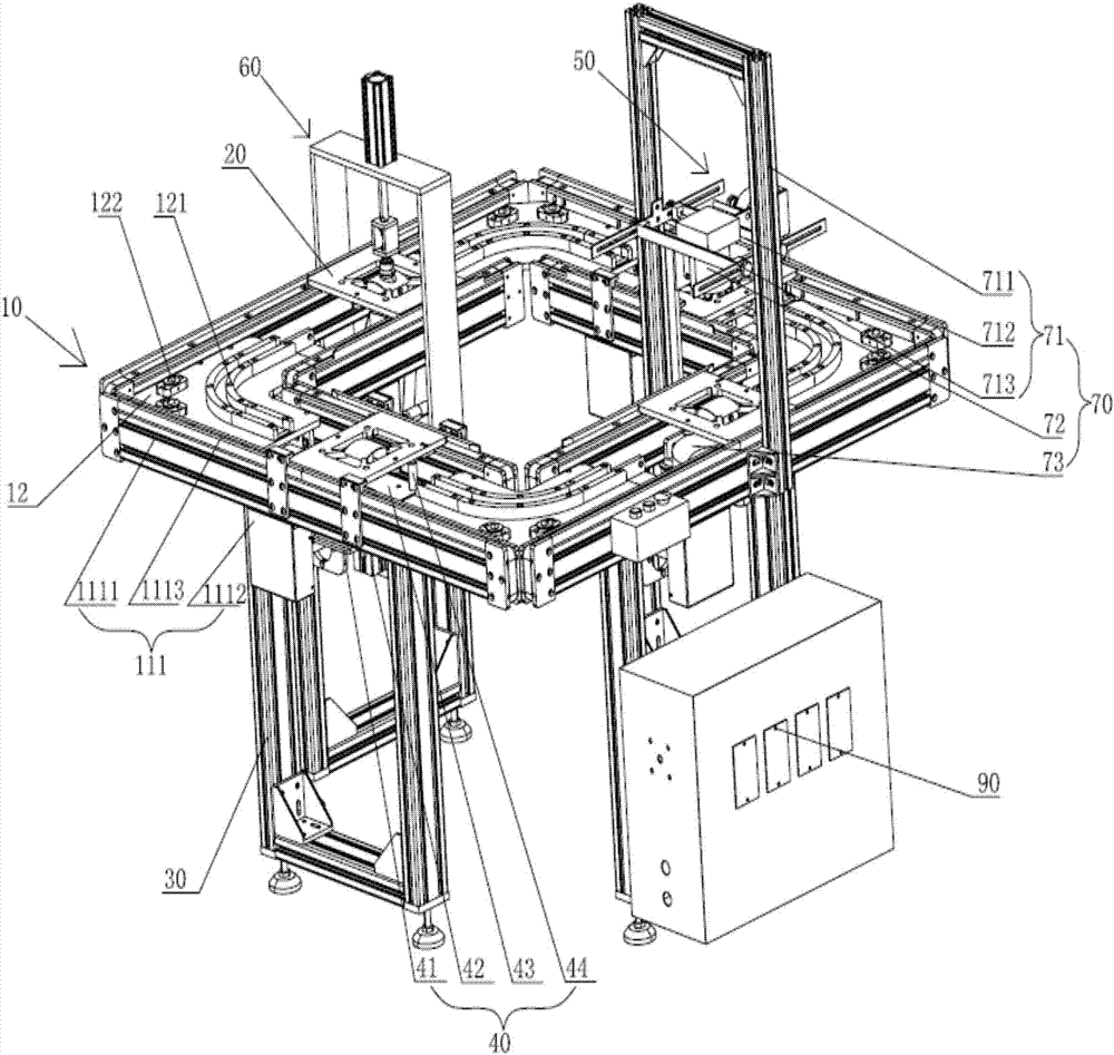
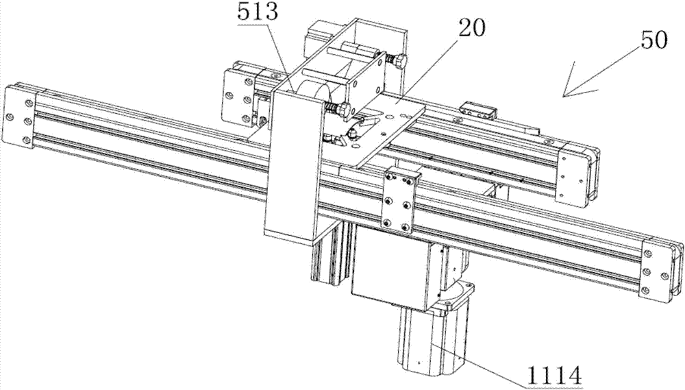
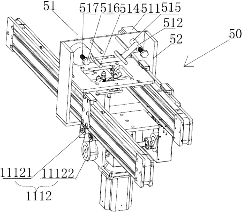
The invention discloses a lens film tearing device, which comprises a transmission platform, several mirror trays arranged on the transmission platform, several support seats arranged under the transmission platform, a lens fixing module, and a lens film tearing device. The film module, the lens lower film tearing module and the lens detection module; the lens fixing module, the lens lower film tearing module, the lens upper film tearing module and the lens detection module are successively arranged on the transmission platform; The table includes four sets of transmission groups arranged in a square shape and a guide slide plate connected between every two adjacent transmission groups to realize the transportation of the mirror tray; the transmission group includes two transmission units facing each other The lens fixing module, the film tearing module under the lens, the film tearing module on the lens and the lens detection module are respectively arranged at the transmission group of each group; a lens film tearing device of the present invention can effectively ensure that the film tearing of the lens Guaranteed constant pre-tightening force, effectively improving the efficiency and quality of film tearing.

Description

technical field [0001] The invention relates to the technical field of mechanical equipment, in particular to a lens film tearing device. Background technique [0002] Lenses are a kind of daily necessities with a very large usage rate. Lenses can overcome the problem of myopia, and can also block ultraviolet rays and infrared rays to reduce eye irritation. After the production of lenses is completed, in order to maintain the smoothness and beauty of the lenses A protective film is pasted on the surface of the lens, and the plastic mold on the surface needs to be torn off in the later processing process. To achieve the best perspective effect of the lens, it is necessary to ensure that there is no stain on the surface of the lens. [0003] The existing lens tearing film generally adopts two methods of manual tearing film and film tearing machine tearing film. During the manual film tearing process, it is easy to touch the lens with human hands, which will cause the lens to b...

Claims


Application Information

Patent Timeline
IPC IPC(8): B32B38/10B32B41/00
CPCB32B38/105B32B41/00
Inventor 李辉
Owner XIAMEN UNIV OF TECH
Learn More