Eureka AIR delivers breakthrough ideas for toughest innovation challenges, trusted by R&D personnel around the world.

Tripod Type Constant Velocity Joint

a constant velocity joint, tripod technology, applied in the direction of yielding couplings, rotary machine parts, couplings, etc., can solve the problems of increasing surface pressure, deteriorating durability of constant velocity joints, and inability to ensure power transmission stability, so as to prevent driving force from being concentrated and generate excessively large frictional forces

Active Publication Date: 2008-03-06
WIA CORP
View PDF4 Cites 3 Cited by
  • Summary
  • Abstract
  • Description
  • Claims
  • Application Information

AI Technical Summary

Benefits of technology

[0020] Accordingly, the present invention has been made to solve the above-mentioned problems occurring in the prior art, and an object of the present invention is to provide a tripod type constant velocity joint which can form a plurality of contact parts between a polyhedral trunnion having at least two polygonal surfaces and the inner surface of an inner roller, so that power transmission stability is ensured and it is possible to prevent driving force from being concentrated on one point, contact pressure from being increased, and two component elements from being brought into contact over their entire surfaces to generate excessively large frictional force.
[0021] Another object of the present invention is to provide a tripod type constant velocity joint in which portions implementing limited relative movement can be reliably lubricated using the straight portions of a polyhedral trunnion to decrease frictional force, suppress axial force generation, reduce vibration of a vehicle, and improve durability of the vehicle.
[0026] According to another aspect of the present invention, a non-contact corner portion is formed on the trunnion between contact parts so that lubricant can be reliably provided to portions which implement limited relative movement.
[0028] According to another aspect of the present invention, a retainer portion for preventing release of the needle rollers and the inner roller is integrally formed on one end of the circumferential outer surface of each inner roller; and a retainer ring and a retainer clip are mounted to the other end of the circumferential outer surface of each inner roller such that they are spaced apart from the needle rollers and the inner roller by a distance which allows the needle rollers and the inner roller to be sufficiently moved in an axial direction of the outer roller.
[0031] According to another aspect of the present invention, a retainer portion for preventing release of the needle rollers and the inner roller is integrally formed on one end of a circumferential inner surface of each outer roller; and wherein a retainer ring and a retainer clip are mounted to the other end of the circumferential inner surface of each outer roller such that they are spaced apart from the needle rollers and the inner roller by a distance which allows the needle rollers and the inner roller to be sufficiently moved in an axial direction of the outer roller.

Problems solved by technology

However, when the elliptical trunnion 3e and the convex contour of the inner roller 5″ are operationally connected with each other, as can be readily seen from FIGS. 5a and 5b, since the elliptical trunnion 3e and the convex contour of the inner roller 5″ are brought into contact with each other on one point 3f to transmit power, a problem is caused in that surface pressure increases and the durability of the constant velocity joint is deteriorated.
Also, because power is transmitted through point contact, the outer roller 4″ cannot be held parallel in the track groove of the housing 2″, whereby power transmission stability cannot be ensured and the effect of suppressing the creation of additional force components by driving force cannot be guaranteed.

Method used


Image

  • Tripod Type Constant Velocity Joint
  • Tripod Type Constant Velocity Joint
  • Tripod Type Constant Velocity Joint

Examples


first embodiment

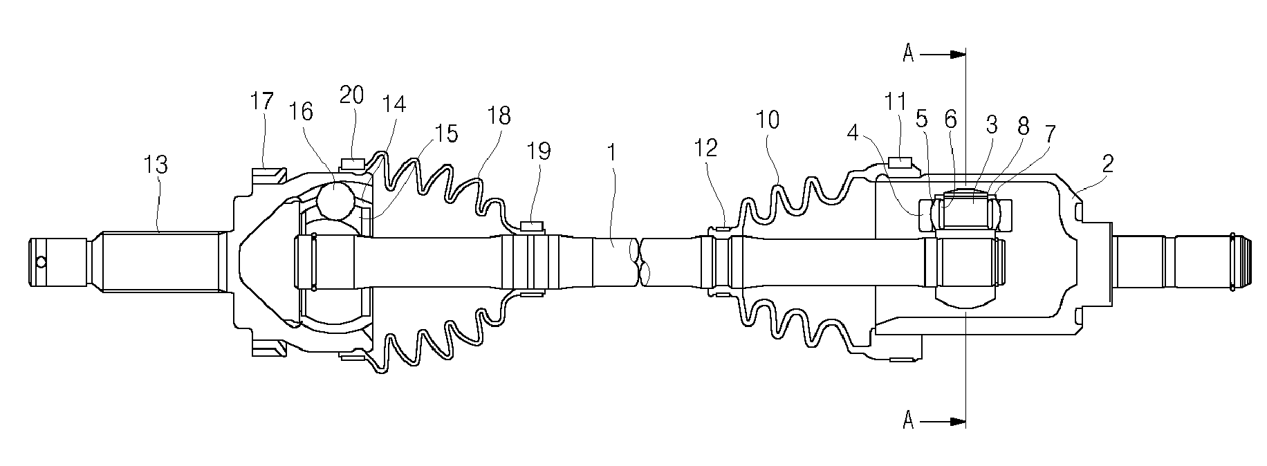
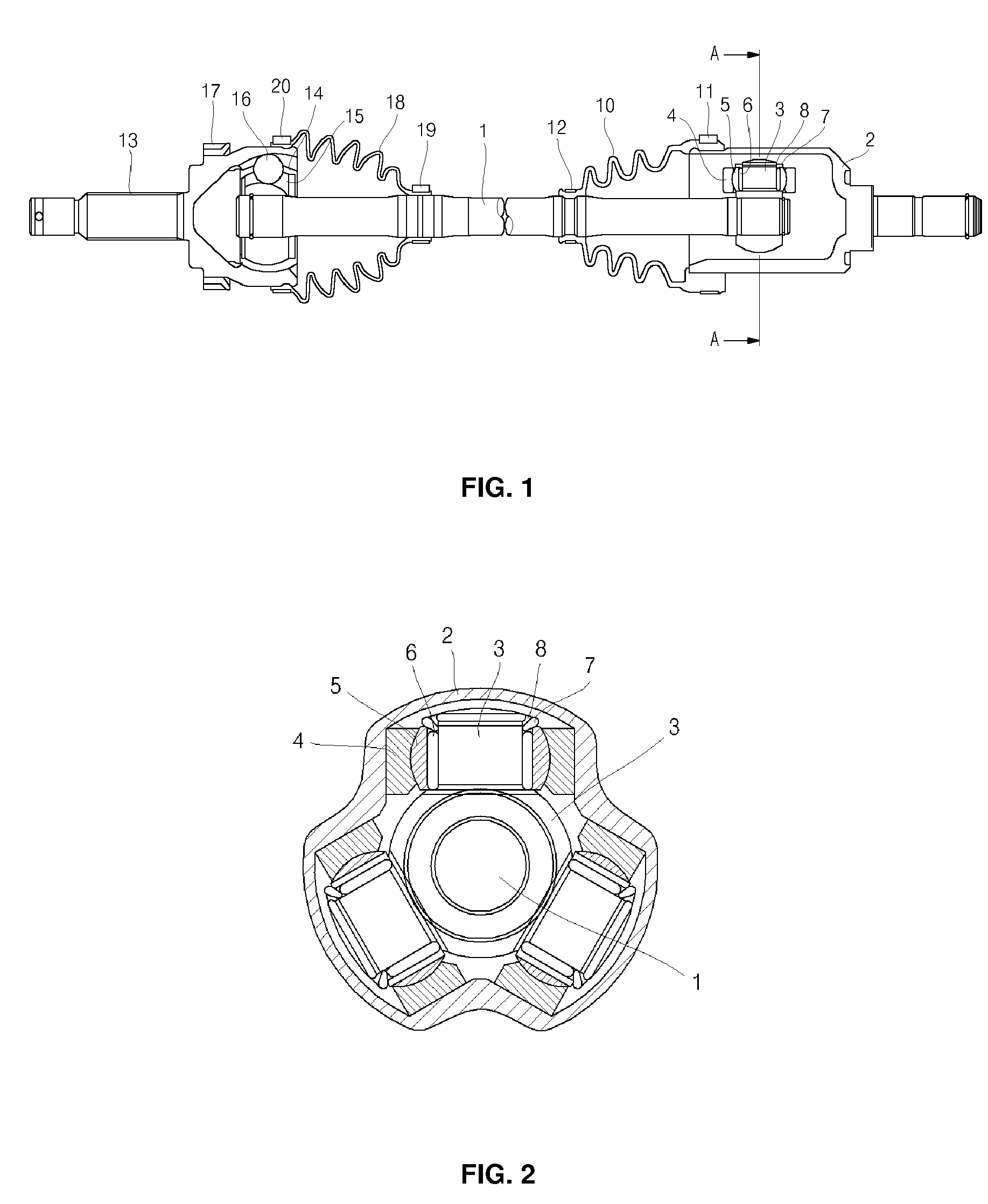
[0071] Referring to FIGS. 10 and 11, the tripod type constant velocity joint in accordance with the present invention comprises a housing 20 having three track grooves 20b which are defined at trisected positions of the housing 20 along the circumferential direction and extend in the radial direction, a spider 21 having three polyhedral trunnions 22 which are projectedly formed at trisected positions of the spider 21 along the circumferential direction to be respectively inserted into the track grooves 20b of the housing 20 and each of which has at least two polygonal surfaces, inner rollers 23 the circumferential inner surface of each of which has a curved contour for surrounding the polyhedral trunnion 22, a plurality of needle rollers 24 assembled to the circumferential outer surface of each inner roller 23, and outer rollers 25 each formed to be rotated through the needle rollers 24, to be moved in the axial direction of the inner roller 23, and to be moved in the axial directio...

second embodiment

[0082] Referring to FIGS. 25 and 26, the tripod type constant velocity joint in accordance with the present invention comprises a housing 20′ having three track grooves 20b′ which are defined at trisected positions of the housing 20′ along the circumferential direction and extend in the radial direction, a spider 21′ having three polyhedral trunnions 22′ which are projectedly formed at trisected positions of the spider 21′ along the circumferential direction to be respectively inserted into the track grooves 20b′ of the housing 20′ and each of which has at least two independent contact points or contact surfaces on each side and at least four independent contact points or contact surfaces on both sides, inner rollers 23′ the circumferential inner surface of each of which has a curved contour for surrounding the polyhedral trunnion 22′, a plurality of needle rollers 24′ assembled to the circumferential outer surface of each inner roller 23′, and outer rollers 25′ each formed to be ro...

third embodiment

[0092] Referring to FIGS. 35 and 36, the tripod type constant velocity joint in accordance with the present invention comprises a housing 20″ having three track grooves 20b″ which are defined at trisected positions of the housing 20″ along the circumferential direction and extend in the radial direction, a spider 21″ having three polyhedral trunnions 22″ which are projectedly formed at trisected positions of the spider 21″ along the circumferential direction to be respectively inserted into the track grooves 20b″ of the housing 20″ and each of which has at least four surfaces such that at least one independent contact surface is positioned on each side, inner rollers 23″ the circumferential inner surface of each of which has a curved contour for surrounding the polyhedral trunnion 22″, a plurality of needle rollers 24″ assembled to the circumferential outer surface of each inner roller 23″, outer rollers 25″ each formed to be rotated through the needle rollers 24″, to be moved in th...


PUM


Abstract

A tripod type constant velocity joint comprises a housing having three track grooves which are defined at trisected positions of the housing along a circumferential direction and extend in a radial direction; a spider having three polyhedral trunnions which are projectedly formed at trisected positions of the spider along the circumferential direction to be respectively inserted into the track grooves and each of which has at least two polygonal surfaces; inner rollers a circumferential inner surface of each of which has a curved contour for surrounding the polyhedral trunnion; a plurality of needle rollers assembled to a circumferential outer surface of each inner roller; and outer rollers each formed to be rotated through the needle rollers, to be moved in an axial direction of the inner roller, and to be moved in an axial direction of the track groove along a guide surface of the housing.

Description

REFERENCE TO RELATED APPLICATIONS [0001] This is a continuation of pending International Patent Application PCT / KR2006 / 002513 filed on Jun. 28, 2006, which designates the United States and claims priority of Korean Patent Application No. 10-2006-0042572 filed on May 11, 2006, the entire contents of which are incorporated herein by reference.FIELD OF THE INVENTION [0002] The present invention relates to a constant velocity joint, and more particularly to a tripod type constant velocity joint which can form a plurality of contact parts between a polyhedral trunnion having at least two polygonal surfaces and the inner surface of an inner roller, so that power transmission stability is ensured and it is possible to prevent driving force from being concentrated on one point, contact pressure from being increased, and two component elements from being brought into contact over their entire surfaces to generate excessively large frictional force, and in which portions implementing limited ...

Claims


Application Information

Patent Timeline
Patent Type & Authority Applications(United States)
IPC IPC(8): F16D3/26
CPCF16D2003/2026F16D3/2055Y10S464/905F16D3/202F16D3/205
Inventor CHO, JEONG HYUNKIM, DAE HWANLEE, IN SANGPARK, JOUNG SIKAN, SUNG BAEKSHIN, SEUNG MANKANG, HWAN BUM
Owner WIA CORP
Why Eureka
Eureka Blog
Learn More