
Stainless steel vibration motor with recirculating cooling water system

A technology of circulating cooling water and vibrating motors, applied in cooling/ventilation devices, electrical components, electromechanical devices, etc., can solve the problems of shortening the service life of the motor, affecting the normal operation of the motor, affecting the service life of the motor, etc., and achieving a long service life. Effect

Pending Publication Date: 2017-10-24
新乡市通用电机有限公司
View PDF5 Cites 1 Cited by
  • Summary
  • Abstract
  • Description
  • Claims
  • Application Information

AI Technical Summary

Problems solved by technology

[0002] Motors are widely used in various fields, especially in some precision industries or high-temperature industries. The performance requirements of motors are getting higher and higher, and the working hours of motors are getting longer and longer. With the operation of the motor, the motor heats up, and the motor rotor shaft and The loss of lubricating oil in the bearing bracket will increase the internal friction of the bearing in the motor, damage the bearing, cause the motor to burn out, and affect the normal operation of the motor. It needs to be shut down for inspection and maintenance, which takes a long time, the service life of the motor is low, and the productivity is reduced.
[0003] At present, in some special chemical production enterprises, vibration motors need to operate continuously in high-temperature and corrosive environments. Ordinary casting vibration motors have poor corrosion resistance, which affects the service life of the motors. In addition, vibration motors operate in high-temperature environments. The heat dissipation is better achieved through the motor shell. If the heat inside the motor cannot be taken out by the surrounding refrigerant in time, the operating efficiency of the motor will be reduced and the service life of the motor will be shortened.

Method used


Image

  • Stainless steel vibration motor with recirculating cooling water system
  • Stainless steel vibration motor with recirculating cooling water system

Examples


Embodiment Construction

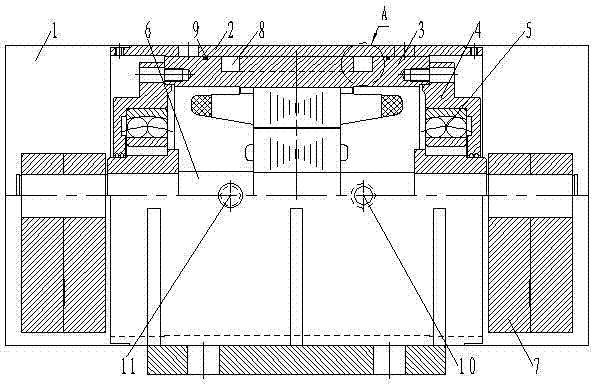
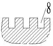
[0013] The technical scheme of the present invention is described in detail in conjunction with the accompanying drawings, a stainless steel vibration motor with a circulating cooling water system, including a stainless steel windshield 1, a stainless steel cylindrical shell 2, a cylindrical inner shell 3, an end cover 4, a bearing 5, and a rotor The shaft 6 and the eccentric block 7, wherein the bearing 5 is embedded in the bearing chamber of the end cover 4, the rotor shaft 6 is installed inside the cylindrical inner shell 3 and the two sides of the rotor shaft 6 are respectively fixed on the bearing 5 and pass through the The end cover 4 and the two ends of the rotor shaft 3 are fixed with eccentric blocks 7 through keys, and the outer wall of the cylindrical inner shell 3 is provided with a spiral flow channel 8 along the circumferential direction, and the outer walls of the cylindrical inner shell 3 on both sides of the spiral flow channel 8 are respectively There is a sea...


PUM


Abstract

The invention discloses a stainless steel vibration motor with a recirculating cooling water system. A bearing is embedded into a bearing housing of an end cover; a rotor shaft is arranged in a cylindrical inner shell and is fixed on the bearing and penetrates through the end cover; the tail end of the rotor shaft is fastened with an eccentric block through a key; a spiral channel is arranged in the outer wall of the cylindrical inner shell along a circumferential direction; a stainless steel cylindrical outer shell and the cylindrical inner shell have a seal fit through O-shaped sealing rings; a stainless steel fan housing and a sealing element at the end of the stainless steel cylindrical outer shell have an interference fit and are fastened through bolts; a water inlet pipe is connected to one end of the spiral channel through a water inlet; and a water outlet pipe is connected to the other end of the spiral channel through a water outlet. According to the stainless steel vibration motor, a problem of motor burnout caused by loss of bearing oil in the motor due to inadequate heat dissipation of the existing vibration motor is effectively solved, and meanwhile, a sealing cavity formed by the stainless steel fan housing and the stainless steel fan housing is used, so that the service life of the motor in the high-temperature and corrosive environments can be effectively prolonged.

Description

technical field [0001] The invention belongs to the technical field of horizontal vibration motors, and in particular relates to a stainless steel vibration motor with a circulating cooling water system. Background technique [0002] Motors are widely used in various fields, especially in some precision industries or high-temperature industries. The performance requirements of motors are getting higher and higher, and the working hours of motors are getting longer and longer. With the operation of the motor, the motor heats up, and the motor rotor shaft and The loss of lubricating oil in the bearing bracket will increase the internal friction of the bearing in the motor, damage the bearing, cause the motor to burn out, and affect the normal operation of the motor. It needs to be shut down for inspection and maintenance, which takes a long time, the service life of the motor is low, and the productivity is reduced. [0003] At present, in some special chemical production ente...

Claims


Application Information

Patent Timeline
IPC IPC(8): H02K9/19H02K5/20H02K5/04H02K5/10
CPCH02K5/04H02K5/10H02K5/20H02K9/19
Inventor 赵久魁
Owner 新乡市通用电机有限公司
Learn More