


Quick Research
Generate reliable direction feasibility study reports for your R&D in just a few steps.

Technical Q&A
Discover and master advanced knowledge NOW. Basics, ideas, possibilities, all at once.

Find Solutions
As an expert in R&D theories, this can generate solutions to your technical problems instantly.

Evaluate Feasibility
Analyze your overall solution with one click, know your potential R&D risks in advance.

Monitor Landscape
Get weekly tech updates, stay abreast of the latest tech innovations and key insights.
Sealing and blocking device and method for geothermal holes only extracting heat rather than water
A plugging device and geothermal technology, applied in earthwork drilling, sealing/isolation, wellbore/well parts, etc., can solve problems such as drinking water pollution, achieve good fluidity, good plugging effect, and good construction performance Effect
- Summary
- Abstract
- Description
- Claims
- Application Information
AI Technical Summary
Problems solved by technology
Method used
Image

Examples
preparation example Construction
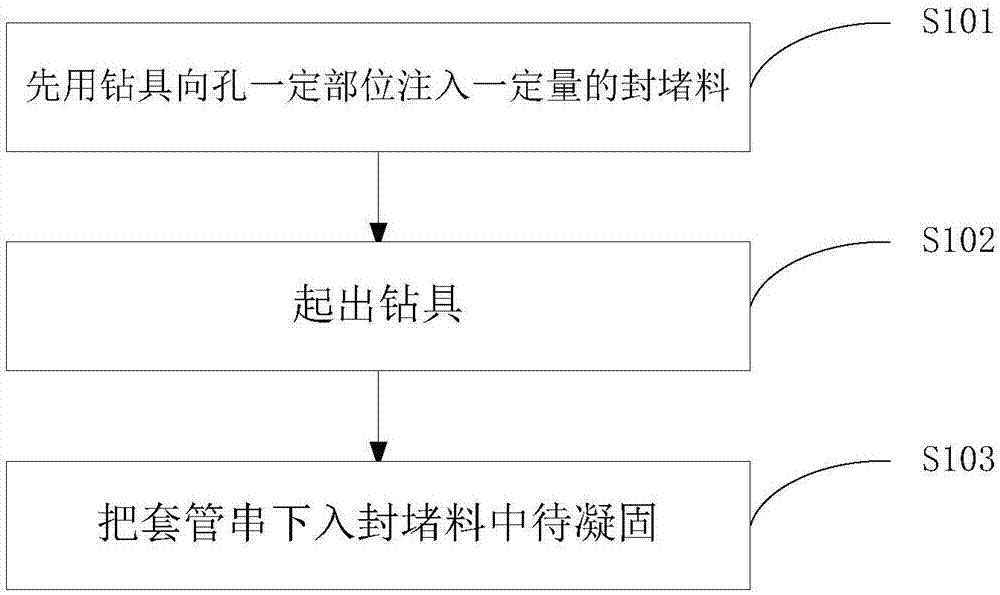
[0057] As a preferred embodiment of the present invention, the preparation method of the plugging material includes:
[0058] Step 1: Take 60-80 parts of Portland cement clinker, 10-20 parts of sulphoaluminate cement, 3-6 parts of bentonite, 0.2-0.5 parts of hydroxyethyl cellulose ether, and 30-20 parts of polymer emulsion according to mass percentage. 40 parts, 3-5 parts of plasticizer, 2-3 parts of defoamer, 0.5-1 part of thickener PRM-300, 20-25 parts of 8# quartz sand; mix and stir evenly to obtain an inorganic precipitation system for use ;
[0059] Step 2, in parts by mass, take 50-90 parts of resin, 0.5-4 parts of accelerator, 10-30 parts of first filler, and 10-30 parts of second filler; mix and stir evenly to obtain a polymer jelly system for use ;
[0060] Step 3: Take the inorganic precipitation system and the polymer jelly system at a ratio of 1:2 to 3.5 by volume.
[0061] As a preferred embodiment of the present invention, after the plugging material is prepar...
Embodiment 1
[0086] The plugging material includes an inorganic precipitation system and a polymer jelly system; the volume ratio of the inorganic precipitation system to the polymer jelly system is 1:2;
[0087] The inorganic precipitation system consists of 60 parts of Portland cement clinker, 10 parts of sulphoaluminate cement, 3 parts of bentonite, 0.2 parts of hydroxyethyl cellulose ether, 30 parts of polymer emulsion, plasticizer Agent 3, defoamer 2, thickener PRM-3000.5 parts, 8# quartz sand 20 parts;
[0088] The polymer jelly system is composed of a resin, an accelerator and a filler; the filler is composed of a first filler and a second filler; in parts by mass, 50-90 parts of a resin, 0.5-4 parts of an accelerator, and 0.5-4 parts of a first filler. 10-30 parts, 10-30 parts of the second filler.
Embodiment 2
[0090] The plugging material includes an inorganic precipitation system and a polymer jelly system; the volume ratio of the inorganic precipitation system to the polymer jelly system is 1:3.5;
[0091] The inorganic precipitation system consists of 80 parts of Portland cement clinker, 20 parts of sulphoaluminate cement, 6 parts of bentonite, 0.5 parts of hydroxyethyl cellulose ether, 40 parts of polymer emulsion, plasticizer 5 parts of agent, 3 parts of defoamer, 1 part of thickener PRM-300, 2025 parts of 8# quartz sand;
[0092] The polymer jelly system is composed of a resin, an accelerator and a filler; the filler is composed of a first filler and a second filler; in parts by mass, 50-90 parts of a resin, 0.5-4 parts of an accelerator, and 0.5-4 parts of a first filler. 10-30 parts, 10-30 parts of the second filler.
PUM
| Property | Measurement | Unit |
|---|---|---|
| Compressive strength | aaaaa | aaaaa |
| Density | aaaaa | aaaaa |
| Bulk density | aaaaa | aaaaa |
Abstract
Description
Claims
Application Information
 - R&D Engineer
- R&D Manager
- IP Professional
- Industry Leading Data Capabilities
- Powerful AI technology
- Patent DNA Extraction
Browse by: Latest US Patents, China's latest patents, Technical Efficacy Thesaurus, Application Domain, Technology Topic, Popular Technical Reports.
© 2024 PatSnap. All rights reserved.Legal|Privacy policy|Modern Slavery Act Transparency Statement|Sitemap|About US| Contact US: help@patsnap.com