
A converter steel slag treatment device and method

A converter steel slag and processing device technology, applied in the field of steelmaking auxiliary equipment technology, can solve the problems of unsuitable converter for fast-paced production, complex and special composition, low processing efficiency, etc., and achieve reliable and efficient steam recovery, degree of mechanization and slag processing. Efficient and fully processed effects

Active Publication Date: 2020-04-10
北京中冶设备研究设计总院有限公司
View PDF6 Cites 3 Cited by
  • Summary
  • Abstract
  • Description
  • Claims
  • Application Information

AI Technical Summary

Problems solved by technology

[0002] In the existing technology, steel slag is mainly based on the converter process. Steel slag is a by-product of converter steelmaking. Due to its complex and special composition, its effective treatment and utilization has always been a difficult problem in the metallurgical industry, and there are few technologies that can be popularized on a large scale. , the existing steel slag treatment technology is mainly based on the hot stuffing method. The disadvantages of this technology are: low processing efficiency, it takes about 20 hours to stuff the slag once, occupies a large area, causes serious pollution, and is not suitable for the fast-paced production of the converter

Method used


Image

  • A converter steel slag treatment device and method

Examples


Embodiment Construction

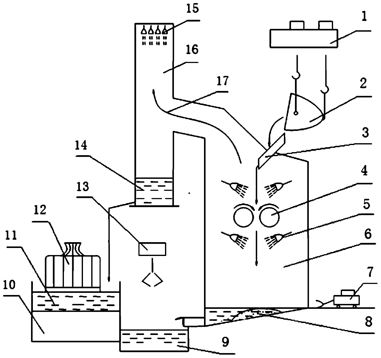
[0008] Embodiments of the present invention are described in further detail below in conjunction with the accompanying drawings: figure 1 It is a structural diagram of a converter steel slag treatment device and method; the device includes a crane 1, a slag tank 2, a chute 3, a hydraulic roller 4, a nozzle a5, a granulation room 6, a forklift 7, a steel slag pool 8, and a bottom filter Pool 9, water pump room 10, water storage tank 11, cooling tower 12, bridge grab crane 13, condensate pool 14, nozzle b15, condensate chimney 16; crane hook 1 is connected to slag tank 2; slag tank 2 outlet is connected to the chute 3 inlet positions are connected; the outlet position of chute 3 is connected with the upper side of the hydraulic roller 4; the upper and lower sides of the hydraulic roller 4 are symmetrically installed with nozzles a5; the hydraulic roller 4 and the nozzle a5 are set in the granulation inside the granulation room 6; a steel slag pool 8 is installed at the lower par...


PUM


Abstract

The invention relates to a converter steel slag treatment device which comprises a crown block, a slag ladle, a chute, a forklift, a steel slag pool, a bottom filtering pool, a water pump house, a water storage tank, a cooling tower, a bridge-type grab crane, a chimney, a hydraulic roller couple, nozzles, a granulating room and a condensate water tank, wherein a lifting hook of the crown block is connected with the slag ladle, the outlet of the slag ladle is connected with the inlet of the chute, and the outlet of the chute is connected with the upper part of the hydraulic roller couple; nozzles a are symmetrically arranged on the two sides of the upper part and the two sides of the lower part of the hydraulic roller couple, and the hydraulic roller couple and the nozzles a are all arranged in the granulating room; the steel slag pool is arranged at the lower part of the granulating room, and the forklift is arranged on the outer side of the lower part of the granulating room. The invention further discloses a converter steel slag treatment method. The flow of the method is as follows: steel slag dumping, steel slag crushing, steel slag granulating, slag washing water filtering and vapor condensation recovery. The converter steel slag treatment device has the advantages of high slag treatment efficiency, compact occupied area, energy conservation, environment protection and no pollution, adapts the fast-paced production mode of a converter, is good for magnetic separation extracting of grain steel and comprehensive application of grain slag, and has remarkable economical benefit.

Description

Technical field: [0001] The invention relates to the technical field of steelmaking auxiliary equipment, in particular to a device and method for processing converter steel slag. Background technique: [0002] In the existing technology, steel slag is mainly based on the converter process. Steel slag is a by-product of converter steelmaking. Due to its complex and special composition, its effective treatment and utilization has always been a difficult problem in the metallurgical industry, and there are few technologies that can be popularized on a large scale. , the existing steel slag treatment technology is mainly based on hot stuffing method, the disadvantages of this technology are: low processing efficiency, it takes about 20 hours to stuff slag once, occupies a large area, causes serious pollution, and is not suitable for fast-paced production of converters. With the continuous deepening of research in recent years and the increasing attention to environmental protect...

Claims


Application Information

Patent Timeline
Patent Type & Authority Patents(China)
IPC IPC(8): C21B3/06C21B3/08
CPCC21B3/06C21B3/08Y02W30/50
Inventor 林杨王洋张盟张金良辛向东续飞飞季乐乐王晖
Owner 北京中冶设备研究设计总院有限公司
Learn More