Polishing brush for photovoltaic module

A photovoltaic module and polishing brush technology, which is applied to grinding/polishing equipment, surface polishing machine tools, brushes, etc., can solve the problems of affecting the appearance and use effect, and the uneven surface of photovoltaic modules, and achieve fast and convenient polishing work. Simple, practical effects

Inactive Publication Date: 2017-10-24
安徽中柜智能科技有限公司
View PDF7 Cites 1 Cited by
  • Summary
  • Abstract
  • Description
  • Claims
  • Application Information

AI Technical Summary

Problems solved by technology

[0006] In the above-mentioned photovoltaic module cutting work, the surface of the photovoltaic module caused by cutting often appears uneven, which affects its appearance and use effect

Method used


Image

  • Polishing brush for photovoltaic module
  • Polishing brush for photovoltaic module

Examples


Embodiment Construction

[0020] In order to have a further understanding and understanding of the structural features of the present invention and the achieved effects, the preferred embodiments and accompanying drawings are used for a detailed description, as follows:

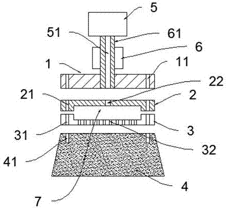
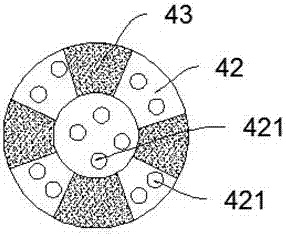
[0021] as attached Figure 1~2 As shown, a polishing brush for photovoltaic modules includes a water tank 5, a rotating shaft 61, a fixed layer 1, an upper concave layer 2, a lower concave layer 3 and a polishing layer 4; the water tank 5, the rotating shaft 61, the fixed layer 1, and the upper concave surface Layer 2, lower concave surface layer 3 and polishing layer 4 are arranged on the coaxial center line in order from top to bottom; the rotating shaft 61 is longitudinally provided between the water tank 5 and the fixed layer 1, and the water tank 5 and the The rotating shaft 61 between the fixed layers 1 is provided with a drive motor 6; the rotating shaft 61 is provided with a liquid inlet pipe 51 coaxially arranged with the rot...


PUM


Abstract

A polishing brush for a photovoltaic module comprises a water channel, a rotating shaft, a fixing layer, an upper concave surface layer, a lower concave surface layer and a polishing layer which are co-axially arranged from top to bottom, wherein the rotating shaft is longitudinally arranged between the water channel and the fixing layer; a driving motor is arranged on the rotating shaft between the water channel and the fixing layer; and a liquid-in pipe coaxial with the rotating shaft is arranged on the rotating shaft. The polishing brush has the following beneficial effects: (1) the polishing brush is simple in structure and high in practicability, and the water channel can provide a polishing solution for a groove area, so that inconvenience caused by manually adding the polishing solution in the groove area is avoided; and (2) under the action of the driving motor, the polishing layer achieves the function of quick rotation, so that the polishing work is quick and convenient and saves both time and labor.

Description

technical field [0001] The invention belongs to the technical field of new energy, and in particular relates to a polishing brush for a photovoltaic module. Background technique [0002] Photovoltaic modules (commonly known as solar panels) are made of solar cells (two specifications of the whole piece: 125*125mm, 156*156mm, 124*124mm, etc.) or solar panels of different specifications cut by a laser cutting machine or a steel wire cutting machine. Batteries are assembled together. Since the current and voltage of a single solar cell are very small, then we first connect them in series to obtain a high voltage, and then connect them in parallel to obtain a high current, and then output it through a diode (to prevent current return). [0003] And package them on a stainless steel, aluminum or other non-metal frame, install the glass on the top and the back plate on the back, fill with nitrogen, and seal. [0004] The whole is called a module, that is, a photovoltaic module o...

Claims


Application Information

Patent Timeline
Patent Type & Authority Applications(China)
IPC IPC(8): B24B29/00B24B41/04B24B57/02B24B47/12A46B13/04
CPCB24B29/005A46B13/04A46B2200/3086B24B41/04B24B47/12B24B57/02
Inventor 孙文生孙传涛
Owner 安徽中柜智能科技有限公司
Why Eureka
Try Eureka