
Ceramic electric leakage test machine

A testing machine and ceramic technology, applied in the field of ceramics, can solve problems such as cumbersome and complicated steps, reduce work efficiency, and reduce user safety hazards, and achieve the effects of improving safety factor, reducing labor intensity, and improving efficiency

Inactive Publication Date: 2017-10-20
YANGZHOU BAOAMAC ELECTRONICS
View PDF0 Cites 3 Cited by
  • Summary
  • Abstract
  • Description
  • Claims
  • Application Information

AI Technical Summary

Problems solved by technology

[0002] Ceramics are widely used. In addition to being used in tableware and decoration, ceramics also play an important role in the development of science and technology. Ceramics also play a pivotal role in the power industry. In terms of power, they are mainly used for high and low voltage transmission Insulators on the line, bushings for motors, post insulators, low-voltage electrical appliances and lighting insulators, as well as insulators for telecommunications, radio insulators, etc. However, if the ceramic processing is not qualified, the residual minerals inside may cause electrical connection. As a result of personal safety, the existing devices are cumbersome and complicated in the inspection of ceramic leakage. Generally, a capacitor withstand voltage tester is used, which is not convenient for ordinary operators to perform inspections, which is a waste of time. At this time, only one ceramic can be detected at a time, which is not convenient for multiple detection operations at one time, which reduces the work efficiency. Although the user will wear anti-electric gloves when using the device, it is not convenient for the user to detect the integrity of the gloves. Sex, inconvenient to reduce the safety hazards of users

Method used


Image

  • Ceramic electric leakage test machine

Examples


Embodiment Construction

[0018] The following will clearly and completely describe the technical solutions in the embodiments of the present invention with reference to the accompanying drawings in the embodiments of the present invention. Obviously, the described embodiments are only some, not all, embodiments of the present invention. Based on the embodiments of the present invention, all other embodiments obtained by persons of ordinary skill in the art without making creative efforts belong to the protection scope of the present invention.

[0019] see figure 1 , the present invention provides a technical solution:

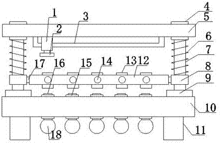
[0020] A ceramic leakage tester, comprising a first fixed plate 5 and a horizontal plate 12, a slide bar 3 is fixedly installed on the lower surface of the first fixed plate 5, a power supply 1 is sleeved on the surface of the slide bar 3, and the power supply 1 1 is slidably connected with the slide bar 3, and a push block 2 is fixedly installed on the lower side of the power supply...


PUM


Abstract

The invention aims to solve a problem that direct contact with to-be-tested ceramics is required by test on multiple ceramics existing in a device in the prior art and discloses a ceramic electric leakage test machine. The ceramic electric leakage test machine comprises a first fixing board, a power source, a push block, a sleeve, a spiral spring, a conductive rod, a first fixed cylinder, a screw, a fixing block, a connection rod, second fixed cylinders, a fixing ring, a vertical sliding rod and a transverse board, wherein a lower end of the fixing block is fixedly equipped with the second fixing board, and a lower end of the first fixed cylinder is equipped with a bulb. The test machine is advantaged in that through controlling the quantity of the second fixed cylinders, during use, test on the multiple-ceramic electric leakage test machine can be rapidly better carried out, single-ceramic operation test carried out by a user can be avoided, labor intensity of the user is reduced, work efficiency is improved, through movable power source connection, direct contact between the user and the ceramic electric leakage test machine is better realized, and a safety coefficient of the user is improved.

Description

technical field [0001] The invention relates to the technical field of ceramics, in particular to a ceramic leakage tester. Background technique [0002] Ceramics are widely used. In addition to being used in tableware and decoration, ceramics also play an important role in the development of science and technology. Ceramics also play a pivotal role in the power industry. In terms of power, they are mainly used for high and low voltage transmission Insulators on the line, bushings for motors, post insulators, low-voltage electrical appliances and lighting insulators, as well as insulators for telecommunications, radio insulators, etc. However, if the ceramic processing is not qualified, the residual minerals inside may cause electrical connection. As a result of personal safety, the existing devices are cumbersome and complicated in the inspection of ceramic leakage. Generally, a capacitor withstand voltage tester is used, which is not convenient for ordinary operators to pe...

Claims


Application Information

Patent Timeline
Patent Type & Authority Applications(China)
IPC IPC(8): G01R31/02
CPCG01R31/50
Inventor 夏磊
Owner YANGZHOU BAOAMAC ELECTRONICS
Learn More