
Robot grabbing part applied to engine assembling production line

A technology for assembly production lines and robot arms, which is applied in the directions of manipulators, chucks, manufacturing tools, etc. It can solve the problems of inconvenient replacement and installation, fewer types of workpieces, and insufficient intelligence, and achieve the effect of easy replacement and installation and various clamping methods.

Pending Publication Date: 2017-10-20
GUANGZHOU SEAHAWN IND ROBOTICS
View PDF7 Cites 9 Cited by
  • Summary
  • Abstract
  • Description
  • Claims
  • Application Information

AI Technical Summary

Problems solved by technology

[0005] The patent name is a multifunctional robot gripper (publication number is CN204772566U ), which discloses a multifunctional robot gripper, including a base, a clamping cylinder, a fixed gripper and a movable gripper, the fixed gripper is installed on the front end of the base, and the movable gripper is installed on the base through the clamping cylinder On the seat and above the fixed grip, a turning device is installed on the movable grip, and a protection device is installed on the clamping cylinder, the protection device includes a clamping air circuit and an unclamping air circuit, and a clamping air circuit and an unclamping air circuit They are respectively connected to the two ends of the clamping cylinder. An exhaust valve is arranged on the release air circuit, and the clamping air circuit and the release air circuit are connected through a pilot-operated exhaust throttle valve. In the workshop, it is inconvenient to replace and install, and there are few types of workpieces suitable for processing, and the intelligence is not enough

Method used


Image

  • Robot grabbing part applied to engine assembling production line
  • Robot grabbing part applied to engine assembling production line
  • Robot grabbing part applied to engine assembling production line

Examples


Embodiment approach

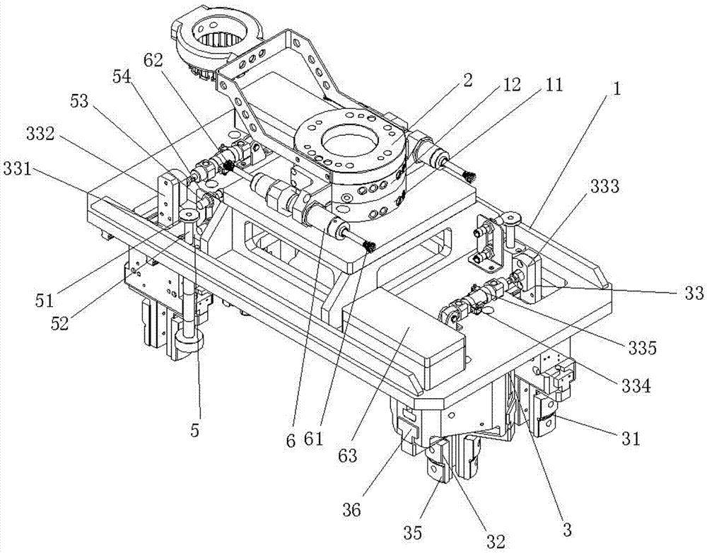
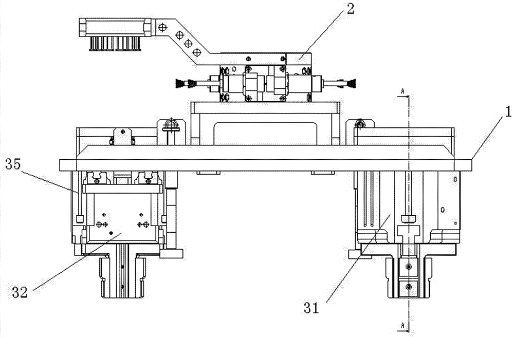
[0031] The invention provides a transmission mechanism 33 An embodiment of the transmission mechanism 33 Includes activity board 331 , movable board connector 332 , floating block 333 and variable pitch cylinder 334 , both hands 31 fixed on movable plate 331 on the flap 331 Via flap connectors 332 with floating block 333 connection, floating block 333 through the cylinder liner 335 with variable pitch cylinder 334 Connect; need to move both grippers 31 , the pneumatic mechanism 4 Control variable pitch cylinder334 , push the floating block 333 move so that the flap connector 332 Mobile, connected to movable plate connectors 332 lower movable panel 331 Simultaneously drive both hands to grasp 31 , so as to stabilize and quickly make the two-handed grip 31 Get some exercise.

[0032] further, hand Grab the body 1 There is also an induction mechanism for sensing and positioning the workpiece 5 and wirele...


PUM


Abstract

The invention relates to the technical field of robot production and assembling, in particular to a robot grabbing part applied to an engine assembling production line. The robot grabbing part comprises a grabbing part body, a clamp is arranged on the grabbing part body and is connected with a flange disc through a clamping sleeve, a grasp mechanism and a pneumatic mechanism are arranged on the grabbing part body, the grasp mechanism comprises a two-piece grasp body and a three-piece grasp body, according to the grabbing part, the clamp is arranged on the grabbing part, and is connected with the flange disc through the clamping sleeve, the grabbing part body can be conveniently mounted on and dismounted from the flange disc on a robot arm through the clamping sleeve, the pneumatic mechanism controls the two-piece grasp body and the three-piece grasp body to move, the large-size workpiece can be conveniently clamped through the two-piece grasp body, transverse clamping and vertical clamping can be achieved, and small-size workpieces can be conveniently clamped through the three-piece grasp body. Replacement and mounting can be facilitated, the workpieces can be fixed and clamped through the two-piece grasp body or the three-piece grasp body, and the clamping manner is diverse.

Description

technical field [0001] The invention relates to the technical field of robot production and assembly, in particular to a robot grip applied to an engine assembly production line. Background technique [0002] An industrial robot is a multi-joint manipulator or a multi-degree-of-freedom machine device for the industrial field. It can perform work automatically and is a machine that realizes various functions by its own power and control capabilities. It can be commanded by humans or run according to pre-programmed programs. Modern industrial robots can also act according to the principles and programs formulated by artificial intelligence technology. [0003] my country's industrial robots started in the last century 1970 early in the year, after 20 Years of development, roughly experienced 3 stages: 70 the budding period of the age, 80 years of development and 90 The period of applicability in years. 1970 my country also launched an artificial satel...

Claims


Application Information

Patent Timeline
Patent Type & Authority Applications(China)
IPC IPC(8): B25J11/00B25J15/08B25J15/10
CPCB25J11/005B25J15/08B25J15/10
Inventor 彭勇超谢伟钢余夏洋左庆科钟叶兴
Owner GUANGZHOU SEAHAWN IND ROBOTICS
Learn More