Fixture for L-shaped thin-wall annular part and machining method

The invention relates to a ring-shaped part and processing method technology, which is applied to the fixture and processing field of L-shaped thin-walled ring-shaped parts, and can solve the problems affecting the uniformity of workpiece wall thickness processing, workpiece size out of tolerance, deformation of L-shaped thin-walled ring-shaped parts, etc. Achieve the effect of reducing workpiece transfer time, fast positioning and alignment, and improving product qualification rate

Inactive Publication Date: 2017-10-20
GUIZHOU LIYANG INT MFG
View PDF10 Cites 11 Cited by
  • Summary
  • Abstract
  • Description
  • Claims
  • Application Information

AI Technical Summary

Problems solved by technology

[0002] At present, in the field of aviation and aerospace industries, a type of L-shaped thin-walled annular parts are commonly used. During the manufacturing process of this type of L-shaped thin-walled annular parts, due to the small wall thickness of the parts, the processing is difficult. During the processing, due to The vibration of machine tools and cutting tools can easily deform such parts. In the prior art, a machine tool is generally used to process a process edge at one end of such parts, and the L-shaped thin-walled ring parts are respectively clamped on two sets of fixtures in turn. The inner circular surface and outer circular surface are processed separately. Using this processing method, due to the large vibration of the machine tool and the tool, it is easy to cause large deformation of the L-shaped thin-walled annular part, and it is difficult to ensure the integrity of the L-shaped thin-walled annular part. The processing accuracy affects the processing quality, and the L-shaped thin-walled ring parts need to be clamped twice in sequence during the processing process, which increases the transfer time of the parts, and each clamping needs to align and position the L-shaped thin-walled ring parts etc., the wall thickness of the L-shaped thin-walled annular parts cannot be detected during the processing, and the contact area between the fixture platen and the parts is small. Due to the large cutting force of the machine tool, the workpiece is prone to slipping and warping under the action of the cutting force of the machine tool. , deformation and other phenomena, especially when the wall thickness of the workpiece is less than 1 mm, the rigidity of the workpiece is very poor, and the deformation of the workpiece during the processing is larger, which affects the uniformity of the workpiece wall thickness processing. The wall thickness of the upper end of the processed part is large, the wall thickness of the lower end is small, and the difference between the wall thickness of the upper end and the lower end is about 0.1 mm to 0.2 mm, which makes the workpiece size out of tolerance and affects the processing quality and performance of the part. Reduce labor efficiency, consume more cutting blanks, need to manufacture two sets of fixtures, and increase production costs

Method used


Image

  • Fixture for L-shaped thin-wall annular part and machining method
  • Fixture for L-shaped thin-wall annular part and machining method
  • Fixture for L-shaped thin-wall annular part and machining method

Examples


Embodiment Construction

[0024] The technical scheme of the present invention will be further described below in conjunction with the accompanying drawings, but the required protection scope is not limited to the description;

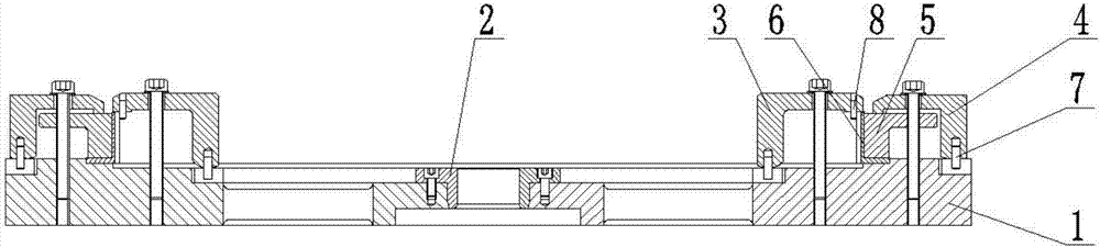
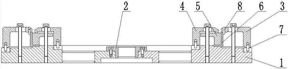
[0025] The invention provides a processing method and a fixture for an L-shaped thin-walled annular part, such as figure 1 , figure 2 As shown, the fixture includes a clamp body 1, a positioning sleeve 2, a pressure plate A3, a pressure plate B4, and a compression sleeve 5. The positioning sleeve 2 is connected to the center of the clamp body 1, and the positioning sleeve 2 is connected to the spindle of the machine tool. The pressure plate A3 and pressure plate B4 are used respectively. The pin 7 is positioned with the end face of the clamp body 1, and the pressure plate A3 and the pressure plate B4 are respectively connected with the clamp body 1 by bolts, and a compression sleeve 5 is also provided at the lower end of the pressure plate B4. Using the technical solution pro...


PUM


Abstract

The invention relates to a fixture for an L-shaped thin-wall annular part and a machining method. The fixture comprises a fixture body, a positioning sleeve, a pressing plate A, a pressing plate B and a pressing sleeve. The positioning sleeve is connected with the center of the fixture body and also connected with a machine tool spindle. The lower end face of the L-shaped thin-wall annular part is flush with the end face of the fixture body. The pressing plate A and the pressing plate B are positioned to the end face of the fixture body through pins and connected with the fixture body through bolts. The upper end face of the L-shaped thin-wall annular part is flatly pressed through the pressing plate A, and the pressing sleeve is flatly pressed on the step face of the L-shaped thin-wall annular part through the pressing plate B. By using the technical scheme provided by the invention, the part is clamped through the fixture and the two pressing plates in sequence, the machining procedures are decreased, and the part transfer time is shortened; and quick positioning and alignment are achieved during clamping of the part, the part rigidity is improved, the wall thickness of the part is machined to be more uniform, the machining precision and the product quality are improved, the production cost is reduced, and the production efficiency is improved.

Description

technical field [0001] The invention relates to the technical field of mechanical processing, in particular to a fixture and a processing method for an L-shaped thin-walled annular part. Background technique [0002] At present, in the field of aviation and aerospace industries, a type of L-shaped thin-walled annular parts are commonly used. During the manufacturing process of this type of L-shaped thin-walled annular parts, due to the small wall thickness of the parts, the processing is difficult. During the processing, due to The vibration of machine tools and cutting tools can easily deform such parts. In the prior art, a machine tool is generally used to process a process edge at one end of such parts, and the L-shaped thin-walled ring parts are respectively clamped on two sets of fixtures in turn. The inner circular surface and outer circular surface are processed separately. Using this processing method, due to the large vibration of the machine tool and the tool, it i...

Claims


Application Information

Patent Timeline
IPC IPC(8): B23Q3/12B23B1/00
CPCB23B1/00B23Q3/12
Inventor 严萍曹连群周雨吴德宁王涛丁海渊
Owner GUIZHOU LIYANG INT MFG
Why Eureka
Try Eureka