
Unmanned aerial vehicle provided with composite fixed wings and capable of vertically taking off

A vertical take-off and fixed-wing technology, applied to vertical take-off and landing aircraft, rotorcraft, unmanned aircraft, etc., can solve problems such as shaking and poor stability, and achieve the effects of reducing vibration, improving stability, and improving stability

Active Publication Date: 2017-10-17
西安锦鹏烨桦信息咨询有限公司
View PDF5 Cites 1 Cited by
  • Summary
  • Abstract
  • Description
  • Claims
  • Application Information

AI Technical Summary

Problems solved by technology

Compared with other methods, the compound wing vertical take-off and landing scheme does not require additional mechanisms and has a simple structure. However, the existing fixed-wing UAVs that can take off vertically have poor stability and serious shaking when taking off.

Method used


Image

  • Unmanned aerial vehicle provided with composite fixed wings and capable of vertically taking off
  • Unmanned aerial vehicle provided with composite fixed wings and capable of vertically taking off
  • Unmanned aerial vehicle provided with composite fixed wings and capable of vertically taking off

Examples


specific Embodiment approach 1

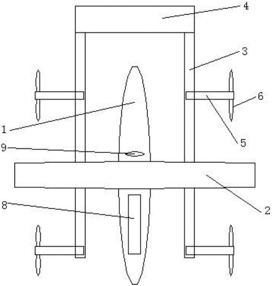
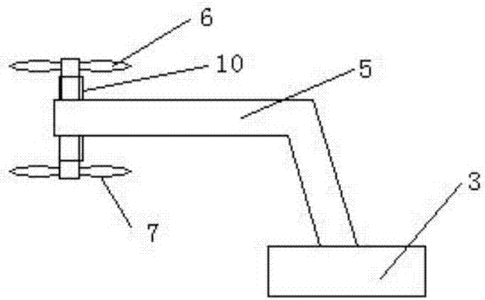
[0031] see as figure 1 and figure 2 As shown, this specific embodiment includes a fuselage 1, a wing 2, a power unit connecting rod 3, an empennage 4, a power unit support rod 5, an upper power unit 6, a lower power unit 7, a driving connection mechanism 8 and a signal receiving mechanism 9 ; The fuselage 1 is provided with a driving connection mechanism 8 and a signal receiving mechanism 9; two wings 2 are symmetrically arranged on both sides of the fuselage 1; a power unit connecting rod 3 is provided on the wing 2; The front and rear ends of the power unit connecting rod 3 are provided with two symmetrical power unit support rods 5; an upper power unit 6 is provided above the power unit support rod 5; a lower power unit is provided below the power unit support rod 5 7; the connection between the upper power unit 6, the lower power unit 7 and the power unit support rod 5 is provided with a universal rotating shaft 10; the power unit connecting rod 3 is inserted at the bott...

specific Embodiment approach 2

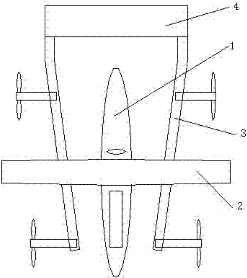
[0032] refer to image 3 and figure 2 The difference between this specific embodiment and specific embodiment 1 is that: the connecting rod 3 of the power unit is set at a certain angle with the wing 2, and the angles presented by the connecting rods 3 on both sides are symmetrical style;

specific Embodiment approach 3

[0033] refer to image 3 and Figure 4 The difference between this specific embodiment and specific embodiment 1 is that: the connecting rod 3 of the power unit is set at a certain angle with the wing 2, and the angles presented by the connecting rods 3 on both sides are symmetrical In addition, the upper power unit 6 and the lower power unit 7 are dislocated up and down, and the edges of the upper and lower propellers are tangent; other structures and connections are the same as those in the first embodiment.

[0034] The principle of the above specific implementation: the wing adopts a composite form, and the form is diversified, the power unit is a combination form, the combined power unit can be combined and operated in any combination, and the flight direction of the aircraft can be changed through the combination of different forms of power units. The empennage of the form and connected with the connecting rod of the power unit can reduce the resistance of the wind.

...


PUM


Abstract

The invention relates to an unmanned aerial vehicle provided with composite fixed wings and capable of vertically taking off and belongs to the technical field of unmanned aerial vehicles. A driving connecting mechanism and a signal receiving mechanism are arranged in a fuselage. The two wings are symmetrically arranged on the two sides of the fuselage. A power unit connecting rod is arranged on each wing. Two symmetrical power unit supporting rods are arranged at the front end and the rear end of each power unit connecting rod correspondingly. Upper power units are arranged above the power unit supporting rods, and lower power units are arranged below the power unit supporting rods. Universal rotating shafts are arranged in the connecting positions of the upper power units, the lower power units and the power unit supporting rods. The unmanned aerial vehicle is reasonable in structural design, convenient to operate, good in flexibility, high in stability, capable of vertically taking off and excellent in take-off stable performance, the fixed wings are arranged in a composite mode, the combination forms of the combined type power units can be selected according to requirements, the combination forms are diverse, and it is beneficial to improve flight stability.

Description

technical field [0001] The invention relates to a composite fixed-wing unmanned aerial vehicle capable of vertical take-off, and belongs to the technical field of unmanned aerial vehicles. Background technique [0002] With the gradual deepening of China's reform and opening up and the rapid development of economic construction, the landforms of various regions have undergone tremendous changes. The existing aerial remote sensing technology can no longer meet the needs of economic development. The new remote sensing technology serves the growing economic construction and cultural undertakings. The technology of using unmanned aircraft as an aerial remote sensing platform is a new type of applied technology developed to meet this need. [0003] UAV aerial photos have the advantages of large scale and wide viewing angle. At present, UAVs are widely used in military reconnaissance, national ecological environment protection, mineral resource exploration, marine environmental ...

Claims


Application Information

Patent Timeline
Patent Type & Authority Applications(China)
IPC IPC(8): B64C27/22B64C29/02
CPCB64C27/22B64C29/02B64U30/20
Inventor 李鹏
Owner 西安锦鹏烨桦信息咨询有限公司
Learn More