A kind of microfluidic control system and its preparation process

A microfluidic system and preparation process technology, applied in the field of microfluidics, can solve problems such as the inability to meet product customization, and achieve the effects of high integration, convenient use and high energy density

Active Publication Date: 2019-07-05
SHENZHEN GRADUATE SCHOOL TSINGHUA UNIV
View PDF6 Cites 0 Cited by
  • Summary
  • Abstract
  • Description
  • Claims
  • Application Information

AI Technical Summary

Problems solved by technology

However, the fields it faces are more electronic products, such as mobile phones, computers, etc. Most of its manufacturing processes still use the manufacturing process of thin-film lithium batteries, which cannot meet the needs of more customizable products.
Looking at the products currently on the market, there is no three-dimensional micro battery with certain flexibility and high capacity.

Method used


Image

  • A kind of microfluidic control system and its preparation process
  • A kind of microfluidic control system and its preparation process
  • A kind of microfluidic control system and its preparation process

Examples


Embodiment 1

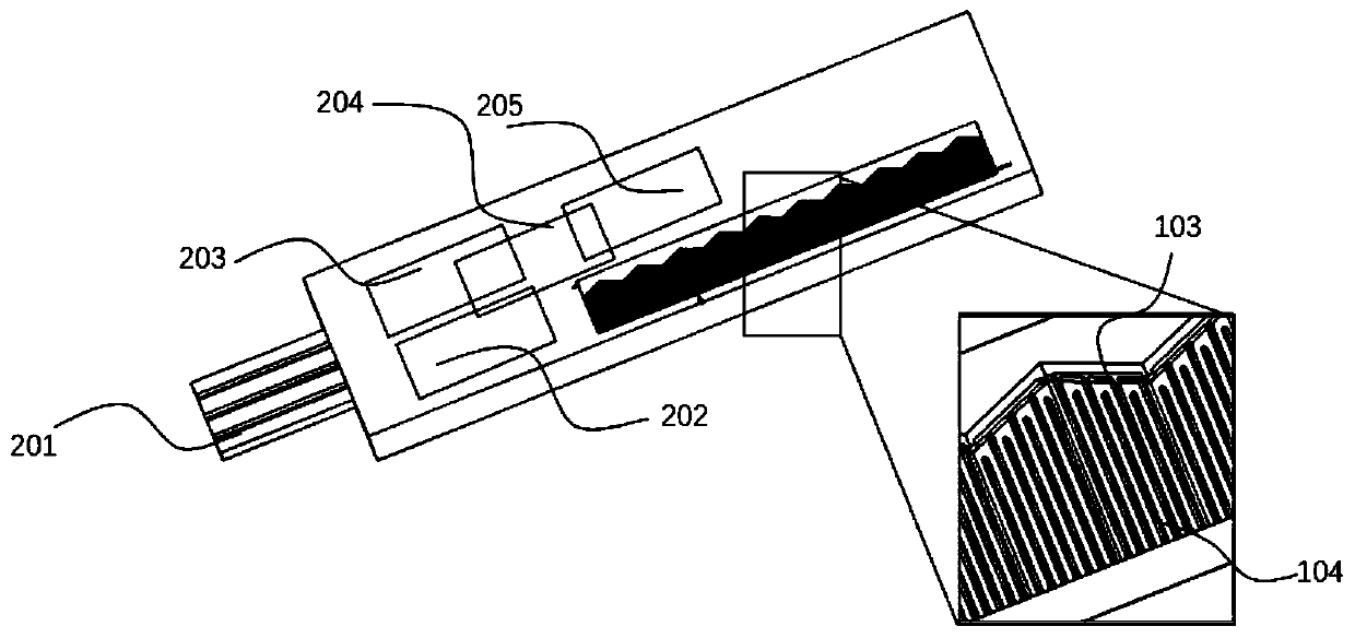
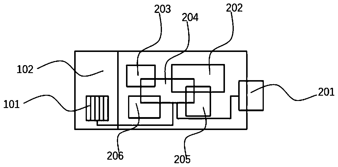
[0046] Making the microfluidic chip: mix Dow Corning 184 colloid and curing agent at a ratio of 10:1 to make PDMS, then put it into the mold for preparing the microfluidic chip substrate 206, and die-cast to obtain the microfluidic chip substrate 206. Then a microfluidic system ( 201 , 202 , 203 , 204 , 205 ) is fabricated on the microfluidic chip substrate 206 by MEMS technology to obtain a microfluidic chip.

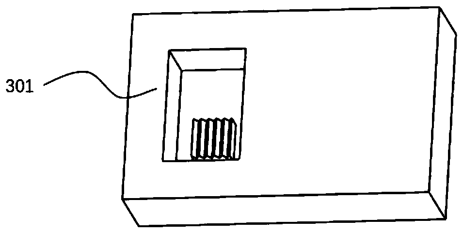
[0047] To make the flexible battery chip substrate 102: mix the colloid of SE1700 and the curing agent at a ratio of 10:1, and place the mold 301 in the tooth-shaped area (such as image 3 shown in ), to obtain a flexible battery chip substrate 102 (such as Figure 4 shown). The resulting flexible battery chip base 102 has a serrated region 101 composed of continuous triangles 105 . The peak height of the triangle 105 is preferably 50-3000 μm, and the base length of the triangle 105 is preferably 100-5000 μm. The plane where the base of the triangle 105 is located i...

Embodiment 2

[0058]Embodiment 2 is basically the same as Embodiment 1, except that the configuration of the positive / negative electrode slurry (108, 109) is different, and its specific process is as follows: (1) active materials such as LFP, LTO and other materials are mixed with ethanol solution according to 0.1g / ml is mixed and transferred to a ball mill for ball milling for 8h, and the rotating speed is set at 500rpm; (2) the mixture of active materials LFP, LTO and ethanol, multi-walled carbon nanotubes, binder HPC (hydroxypropyl cellulose, molecular weight 1,000,000 ), the dispersant pvp was put into the petri dish respectively, and the upper part of the petri dish was sealed with a dust-free paper, put into a vacuum oven at 150°C, baked for 12 hours, took it out and put it into a desiccator for storage; (3) filled with argon In the glove box, take 4g binder HPC and dissolve it in 20ml 1,4-dioxane solution, add 0.5g each time, stir evenly with a glass rod, wrap the lid of the reagent ...


PUM

PropertyMeasurementUnit
thicknessaaaaaaaaaa
diameteraaaaaaaaaa

Abstract

The invention discloses a microfluidic system and a production process thereof. The microfluidic system is mainly composed of a microfluidic chip and a flexible battery chip, the flexible battery chip comprises a substrate and a tooth profile area located on the substrate, a cross-finger type current collector is arranged on the surface of the tooth profile area, the root of the cross-finger type current collector is perpendicular to the rib line of triangular tops of the tooth profile area, the finger part of the cross-finger type current collector is located on two waist surfaces of triangles and is parallel to the rib line of the triangular tops of the tooth profile area, the finger part of the cross-finger type current collector is covered with positive / negative active substances. Three-dimensional printing and the micro-nano machining technology are mainly combined, the three-dimensional battery system which is high in energy density, small in size, high in integration level and capable of repeatedly bending is rapidly produced, the three-dimensional battery system and the microfluidic chip are integrated, and the microfluidic chip can be directly powered.

Description

technical field [0001] The invention belongs to the field of microfluidic technology, and in particular relates to a microfluidic system and a preparation process thereof. Background technique [0002] Microfluidics refers to the technology of manipulating fluid or gas in a channel system with a width of tens of microns to hundreds of microns. The chip-type micro-total analysis system with microfluidic technology as the core and processed by MEMS technology and applied in the fields of biology, chemistry, and biomedicine is called a microfluidic chip. The main advantages of microfluidic chip technology are: small sample size required, high detection efficiency, low cost of use, easy integration with other technical equipment, and good compatibility. The future development direction is to realize portable detection. [0003] However, for a miniaturized system with a high degree of integration, how to find a miniaturized energy supply device that can match it is a problem enc...

Claims


Application Information

Patent Timeline
Patent Type & Authority Patents(China)
IPC IPC(8): B01L3/00B81B7/00B81C3/00
CPCB01L3/502707B81B7/0032B81C3/00
Inventor 弥胜利刘长勇李柏翰孙伟李伟杨帅涛易晓满
Owner SHENZHEN GRADUATE SCHOOL TSINGHUA UNIV
Why Eureka
Try Eureka