Method for smooth and steady floating and descending of moving-coil permanent magnetic planar motor, without position sensor

A permanent magnet plane, moving coil technology, applied to holding devices, instruments, electrical components, etc. using magnetic attraction or thrust, can solve the problems of complex programming, long positioning time, position jitter, etc., to reduce execution errors. , The effect of short positioning time and cost saving

Inactive Publication Date: 2017-10-13
ANHUI UNIVERSITY OF TECHNOLOGY AND SCIENCE
View PDF5 Cites 4 Cited by
  • Summary
  • Abstract
  • Description
  • Claims
  • Application Information

AI Technical Summary

Problems solved by technology

[0004] According to the deficiencies in the prior art above, the technical problem to be solved by the present invention is to propose a method for the smooth lifting and lowering of a moving coil type permanent magnet planar motor without a position sensor. The height control of the existing moving coil type permanent magnet planar motor generally adopts Position feedback PID control, because the mover is generally required to be suspended at a height of 1-4 mm, this method has disadvantages such as complicated programming, long positioning time, and position jitter. The air gap sensor is omitted to save costs, the control is simple, the positioning is stable and the error is small, and the operation is reliable

Method used


Image

  • Method for smooth and steady floating and descending of moving-coil permanent magnetic planar motor, without position sensor
  • Method for smooth and steady floating and descending of moving-coil permanent magnetic planar motor, without position sensor
  • Method for smooth and steady floating and descending of moving-coil permanent magnetic planar motor, without position sensor

Examples


Embodiment Construction

[0021] Below with reference to accompanying drawing, through the description of embodiment, the specific embodiment of the present invention such as the shape of each component involved, structure, mutual position and connection relationship between each part, the effect of each part and working principle, manufacturing process And the method of operation and use, etc., are described in further detail to help those skilled in the art have a more complete, accurate and in-depth understanding of the inventive concepts and technical solutions of the present invention.

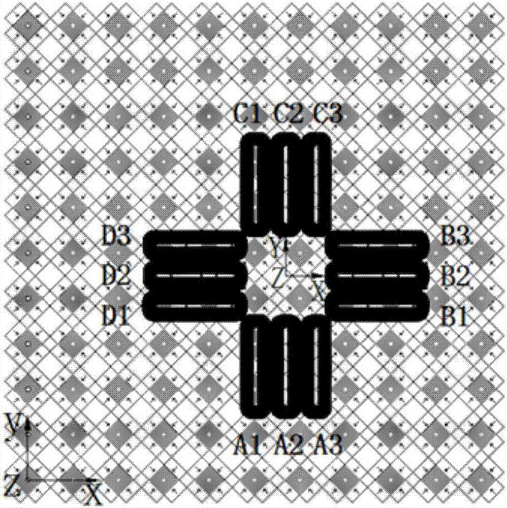
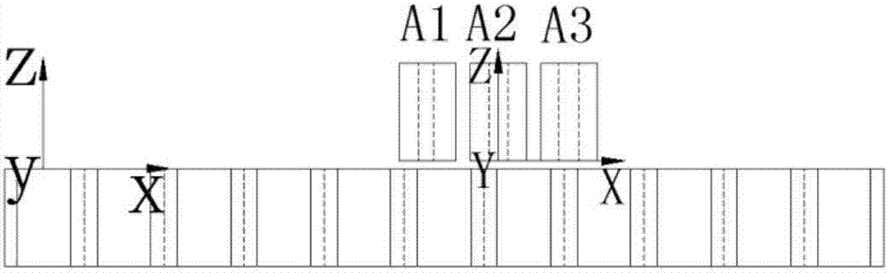
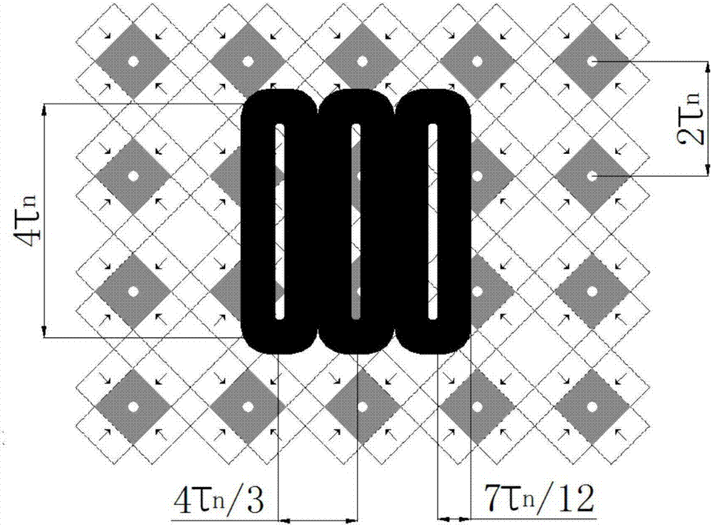
[0022] figure 1 It is a simplified structure diagram of the moving coil permanent magnet planar motor. The coordinate system setting, stator permanent magnet array layout, and mover coil array layout are shown in the figure. The moving coil permanent magnet planar motor is mainly divided into two parts: the stator and the mover. The stator is composed of a two-dimensional Halbach permanent magnet array, which con...


PUM


Abstract

The invention discloses a method for smooth and steady floating and descending of a moving-coil permanent magnetic planar motor, without a position sensor and belongs to the technical field of motor control. When a rotor is controlled to float, an air gap height namely an expected air gap point of expected floating is given, and a false air gap point height is computed according to the air gap height of the expected floating; then, currents are distributed to coil arrays, so the rotor becomes balanced at the fault air gap point; after delay of a threshold period, the rotor moves to the expected air gap point, and the speed is zero; and at this moment, currents are distributed to the coil arrays, so the rotor is balanced at the expected air gap point, and the rotor is stably floated at the expected air gap point. When the rotor is controlled to descend, the false air gap point currents of the rotor, which are the same with the currents during floating, are distributed; and after delay of the same threshold period, the rotor moves to the surface of a stator, and the speed is zero. The method has the advantages that an air gap sensor does not need to be used, and the cost is reduced; a complicated positioning program do not need to be compiled, so duration for equipment development and debugging is saved; frequency changing and distribution of currents are not needed; positioning height is accurate; and positioning time is short.

Description

technical field [0001] The invention belongs to the technical field of motor control, and in particular relates to a method for stably lifting and lowering a moving-coil permanent-magnet planar motor without a position sensor, which is suitable for photolithography and packaging of integrated circuits, assembly and packaging of MEMS devices, high-precision plotters, etc. Field of manufacturing equipment positioned flat. Background technique [0002] Because of its ultra-high motion accuracy and two-dimensional operation characteristics, planar motors are widely used in high-precision processing technology, such as lithography and packaging of integrated circuit chips, assembly and packaging of MEMS devices, etc. As a large type of planar motor, moving coil magnetic levitation permanent magnet planar motor has been paid attention to by academic and engineering circles at home and abroad because it meets the characteristics of a new generation of lithography machines that need...

Claims


Application Information

Patent Timeline
Patent Type & Authority Applications(China)
IPC IPC(8): G06F17/50H02N15/00
CPCG06F30/17G06F30/20H02N15/00
Inventor 陆华才阮光正陆昊程聃
Owner ANHUI UNIVERSITY OF TECHNOLOGY AND SCIENCE
Why Eureka
Try Eureka