Concentrated heat radiating type high-power direct-current charger module

A DC charging, high-power technology, applied in charging stations, current collectors, electric vehicle charging technology, etc., can solve problems such as damage to the service life of DC fans, fragile parts, poor heat dissipation, etc., and achieve the effect of improving the IP protection level.

Inactive Publication Date: 2017-10-03
GUANGDONG THOUSANDS OF CITIES & CHARGING STATIONS E VEHICLES OPERATING CO LTD
View PDF5 Cites 14 Cited by
  • Summary
  • Abstract
  • Description
  • Claims
  • Application Information

AI Technical Summary

Problems solved by technology

However, the smaller the size of the DC fan, the weaker the internal parts, easily damaged, and poor heat dissipation. In the active air cooling mode, various factors such as temperature, dust, humidity, oil, mildew, salt spray, and chemicals Seriously damage the service life of the DC fan
[0005] 3. In the DC charging module with a high power density of 15KW, the large-capacity capacitors are all electrolytic aluminum electrolytic capacitors. The temperature rise of a single DC charging module is about 18°C ​​when it is fully loaded and output, and some of them are close to the internal radiator of the module. The temperature rise of the electrolytic capacitor is greater than 30°C, and the high temperature and harsh environment will seriously affect the service life of the aluminum electrolytic capacitor
[0006] 4. The topology of the traditional DC charging module adopts a bridgeless Vienna rectifier circuit and a three-level LLC resonant circuit, and uses a large number of field effect transistors in parallel to achieve high-power output. The structure is complex, there are too many components, and the increase cost
[0007] 5. Other traditional DC charging modules are small in size and low in output power. However, the maximum output power of the main DC charging modules produced in the market is generally 15kw, and the DC charging modules with low power output cannot meet the needs of the market.

Method used


Image

  • Concentrated heat radiating type high-power direct-current charger module
  • Concentrated heat radiating type high-power direct-current charger module

Examples


Embodiment Construction

[0021] The following will clearly and completely describe the technical solutions in the embodiments of the present invention with reference to the accompanying drawings in the embodiments of the present invention. Obviously, the described embodiments are only part of the embodiments of the present invention, not all of them. Based on the embodiments of the present invention, all other embodiments obtained by persons of ordinary skill in the art without creative efforts fall within the protection scope of the present invention.

[0022] It should be noted that the protection of the present invention is the improved application of the topological structure and components of the power supply circuit of the DC charging module.

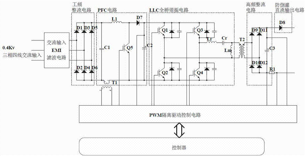
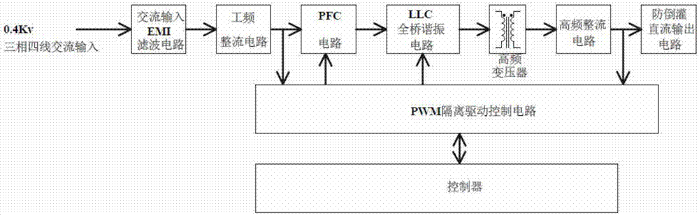
[0023] refer to Figure 1-2 , the invention discloses a DC charging module, which receives an output instruction from a controller of an off-vehicle DC charger, and converts three-phase four-wire AC power into DC power required by an electric vehicle.

...


PUM


Abstract

The invention discloses a concentrated heat radiating type high-power direct-current charger module. The direct-current charger module is used for receiving an output command of an off-board direct-current charger controller and converting three-phase four-wire alternating current into direct current needed by electric vehicles. A main circuit heating power device of the direct-current charger module disclosed by the invention is installed on a heat radiator for concentrated heat radiation, a direct-current charger module controller and a PWM isolation drive circuit are packaged in a heat conduction shell, the heat conduction shell is isolated from the heat radiator to realize heat insulation, and the IP protective level of the controller is improved, so that the reliability is effectively improved; and a direct-current charger circuit adopts an IGBT module or an SIC module, so that the output power and reliability of the direct-current charger module are effectively improved.

Description

technical field [0001] The invention relates to the technical field of charging pile charging, in particular to a concentrated heat dissipation type high-power DC charging module. Background technique [0002] According to the real-time requirements of the electric vehicle battery management system, the DC charger converts the three-phase four-wire 380VAC AC input isolation into the required DC energy (BMS real-time demand voltage and current demand) and charges the battery pack of the electric vehicle. The power conversion part of the DC charger is a DC charging module. The current DC charging module adopts the active air-cooled DC charging module used in the telecommunications room, and its hidden dangers are quite obvious: [0003] 1. In the DC charging module with a high power density of 15KW, a DSP single-chip microcomputer and a digital logic circuit with a relatively high degree of integration are used for sampling control, and the pin spacing of the device is small. ...

Claims


Application Information

Patent Timeline
Patent Type & Authority Applications(China)
IPC IPC(8): H02J7/02H02J7/00B60L11/18
CPCB60L53/30H02J7/0027H02J7/0042H02J7/022H02J2207/20Y02T10/70Y02T10/7072Y02T10/72Y02T90/12
Inventor 霍锦强陈刚梁翔飞白海涛何建华邢庆吴志磊陈航左锦王久平
Owner GUANGDONG THOUSANDS OF CITIES & CHARGING STATIONS E VEHICLES OPERATING CO LTD
Why Eureka
Try Eureka